
Advanced Diagnostics
Advanced Diagnostics - DTC P0153: Front Air/Fuel Ratio (A/F) Sensor (Bank 2, Sensor 1) Malfunction/Slow Response

General Description
The front air/fuel ratio (A/F) sensor (bank 2, sensor 1) has a linear signal output in relation to the oxygen concentration. The powertrain control module (PCM) computes the air/fuel ratio from the front A/F sensor output voltage and uses fuel feedback control to improve exhaust emissions. The PCM compares the response characteristics against the front A/F sensor output. If the total front A/F sensor output is a specified value for a specified time, the PCM detects a deteriorated response and stores a DTC.
Monitor Execution, Sequence, Duration, DTC Type, OBD Status

Enable Conditions
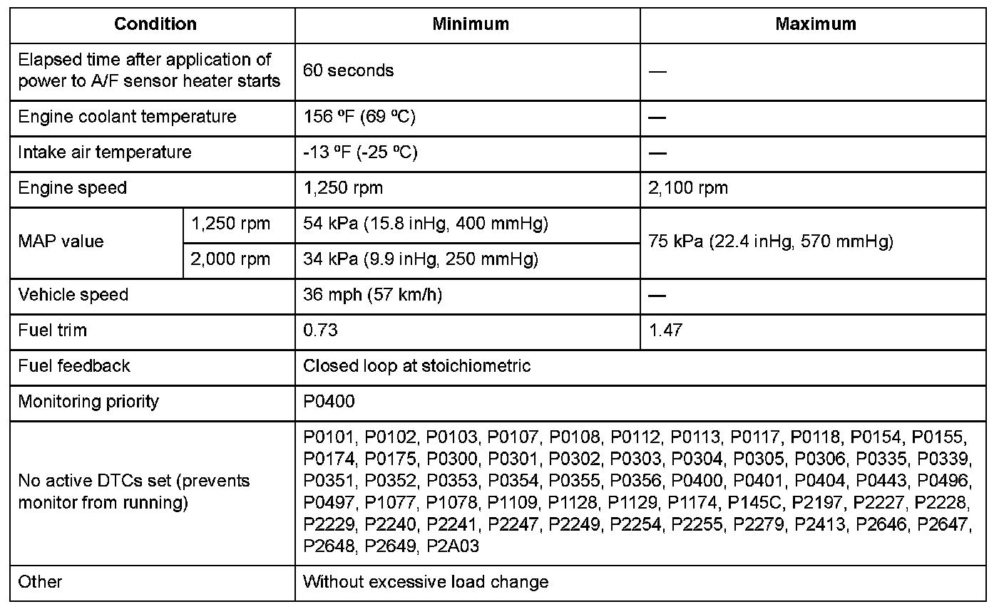
Malfunction Threshold
The total front A/F sensor (bank 2, sensor 1) output value is 34 or less in 6.8 seconds.
Driving Pattern
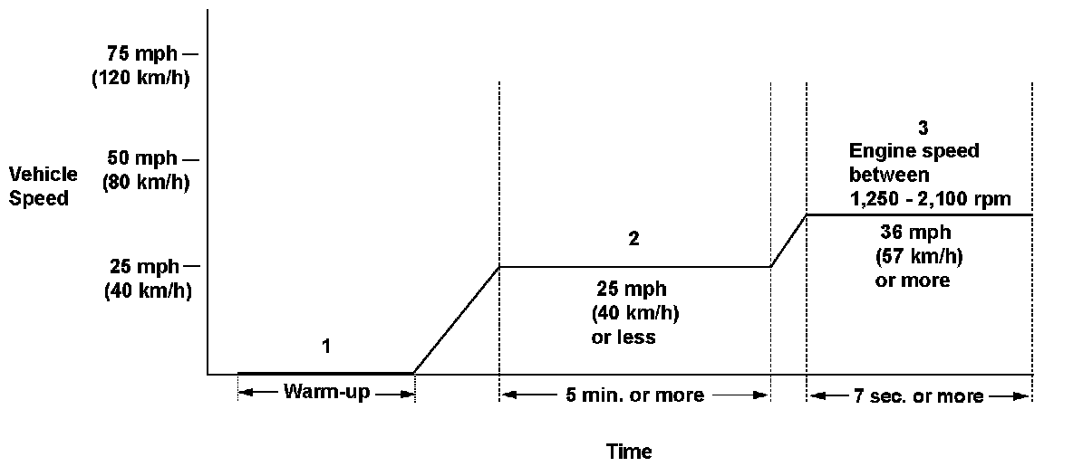
1. Start the engine. Hold the engine speed at 3,000 rpm without load (in P or N) until the radiator fan comes on.
2. Drive the vehicle at a steady speed of 25 mph (40 km/h) or less, for at least 5 minutes.
3. Drive immediately at a steady speed of 36 mph (57 km/h) or more and engine speed between 1,250 - 2,100 rpm for at least 7 seconds.
- Drive the vehicle in this manner only if the traffic regulations and ambient conditions allow.
Diagnosis Details
Conditions for setting the DTC
When a malfunction is detected during the first drive cycle, a Pending DTC is stored in the PCM memory. If the malfunction returns in the next (second) drive cycle, the MIL comes on and a Confirmed DTC and the freeze data are stored.
Conditions for clearing the DTC
The MIL is cleared if the malfunction does not return in three consecutive trips in which the diagnostic runs. The MIL, the Pending DTC, the Confirmed DTC, and the freeze data can be cleared with the scan tool Clear command or by disconnecting the battery.
General Description
The front air/fuel ratio (A/F) sensor (bank 2, sensor 1) has a linear signal output in relation to the oxygen concentration. The powertrain control module (PCM) computes the air/fuel ratio from the front A/F sensor output voltage and uses fuel feedback control to improve exhaust emissions. The PCM compares the response characteristics against the front A/F sensor output. If the total front A/F sensor output is a specified value for a specified time, the PCM detects a deteriorated response and stores a DTC.
Monitor Execution, Sequence, Duration, DTC Type, OBD Status
Enable Conditions
Malfunction Threshold
The total front A/F sensor (bank 2, sensor 1) output value is 34 or less in 6.8 seconds.
Driving Pattern
1. Start the engine. Hold the engine speed at 3,000 rpm without load (in P or N) until the radiator fan comes on.
2. Drive the vehicle at a steady speed of 25 mph (40 km/h) or less, for at least 5 minutes.
3. Drive immediately at a steady speed of 36 mph (57 km/h) or more and engine speed between 1,250 - 2,100 rpm for at least 7 seconds.
- Drive the vehicle in this manner only if the traffic regulations and ambient conditions allow.
Diagnosis Details
Conditions for setting the DTC
When a malfunction is detected during the first drive cycle, a Pending DTC is stored in the PCM memory. If the malfunction returns in the next (second) drive cycle, the MIL comes on and a Confirmed DTC and the freeze data are stored.
Conditions for clearing the DTC
The MIL is cleared if the malfunction does not return in three consecutive trips in which the diagnostic runs. The MIL, the Pending DTC, the Confirmed DTC, and the freeze data can be cleared with the scan tool Clear command or by disconnecting the battery.