
Safety Warning
DIY auto repair can cause serious injury, fire, or vehicle damage. These guides are for informational purposes only. Always follow OEM torque specs, wear PPE, and consult a certified mechanic if you are unsure. You are solely responsible for your safety.
2000 Toyota RAV4 2-Door 2WD L4-2.0L (3S-FE)FACTORY OEM SERVICE PROCEDURE
Input Shaft
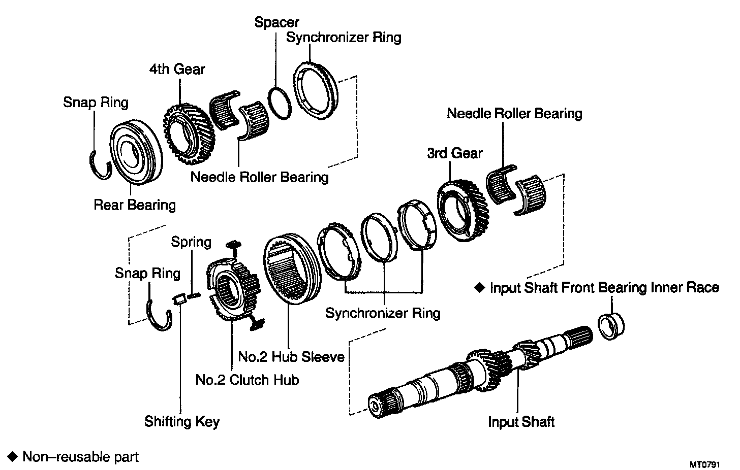
DISASSEMBLY
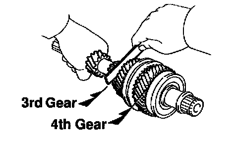
1. MEASURE 3RD AND 4TH GEARS THRUST CLEARANCE
Using a feeler gauge, measure the thrust clearance.
Standard clearance:
3rd gear: 0.10 - 0.35 mm (0.0039 - 0.0138 inch)
4th gear: 0.10 - 0.55 mm (0.0039 - 0.0217 inch)
Maximum clearance:
3rd gear: 0.40 mm (0.0157 inch)
4th gear: 0.60 mm (0.0236 inch)
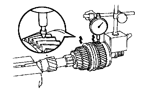
2. CHECK 3RD AND 4TH GEARS RADIAL CLEARANCE
Using a dial indicator, measure the radial clearance between the gear and shaft.
Standard clearance:
3rd gear: 0.009 - 0.053 mm (0.0004 - 0.0021 inch)
4th gear: 0.009 - 0.051 mm (0.0004 - 0.0020 inch)
Maximum clearance:
3rd and 4th gears: 0.070 mm (0.0028 inch)
If the clearance exceeds the maximum, replace the gear, needle roller bearing or shaft.
3. REMOVE SNAP RING
Using 2 screwdrivers and a hammer, tap out the snap ring.
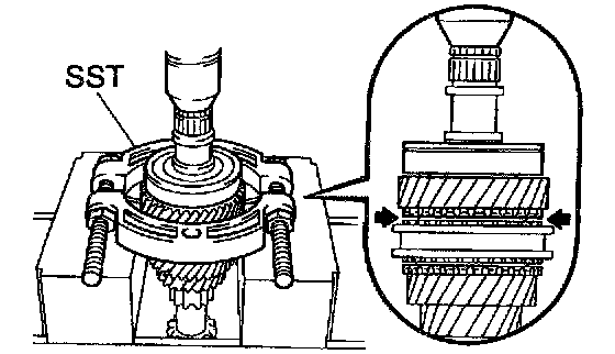
4. REMOVE REAR BALL BEARING AND 4TH GEAR
Using SST and a press, remove the rear bearing.
SST 09950-00020
5. REMOVE NEEDLE ROLLER BEARING, SPACER AND SYNCHRONIZER RING
6. REMOVE SNAP RING
Using 2 screwdrivers and a hammer, tap out the snap ring.
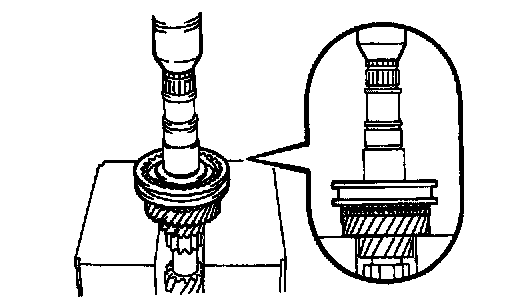
7. REMOVE NO.2 CLUTCH HUB ASSEMBLY, SYNCHRONIZER RING AND 3RD GEAR
Using a press, remove the No.2 hub sleeve, 3rd gear and synchronizer rings.
8. REMOVE NEEDLE ROLLER BEARING
INSPECTION
1. INSPECT 3RD GEAR SYNCHRONIZER RING
a. Check for wear or damage.

b. Check the braking effect of the synchronizer ring. Turn the synchronizer ring in one direction while pushing it to the gear cone. Check that the ring locks.
If it does not lock, replace the synchronizer ring.
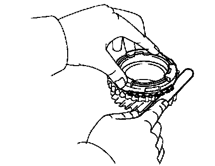
c. Using a feeler gauge, measure the clearance between the synchronizer ring back and gear spline end.
Minimum clearance: 0.7 mm (0.028 inch)
If the clearance is less than the minimum, replace the synchronizer ring.
2. INSPECT 4TH GEAR SYNCHRONIZER RING
a. Check for wear or damage.
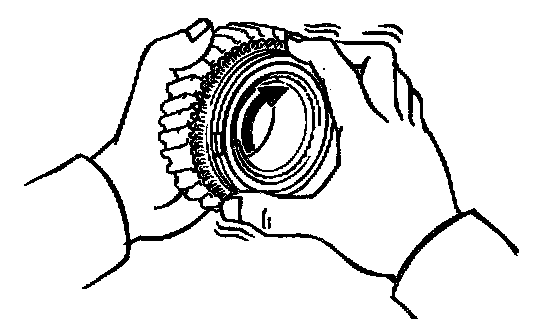
b. Check the braking effect of the synchronizer ring. Turn the synchronizer ring in one direction while pushing it to the gear cone. Check that the ring locks.
If the braking effect is insufficient, apply a small amount of the fine lapping compound between the synchronizer ring and gear cone. Lightly rub the synchronizer ring and gear cone together.
NOTICE: Ensure the fine lapping compound is completely washed off after rubbing.
c. Check again the braking effect of the synchronizer ring.
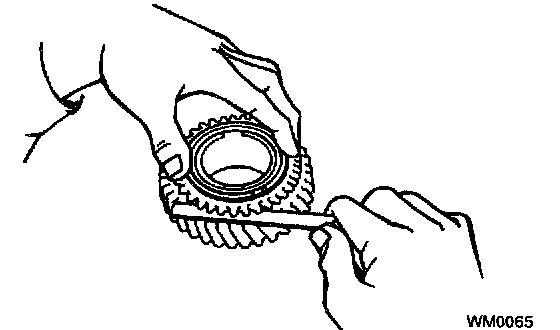
d. Using a feeler gauge, measure the clearance between the synchronizer ring back and spline end.
Minimum clearance: 0.8 mm (0.031 inch)
If the clearance is less than the minimum, replace the synchronizer ring, and apply a small amount of the fine lapping compound on gear cone.
NOTICE: Ensure the fine lapping compound is completely washed off after rubbing.
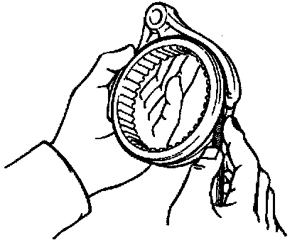
3. MEASURE NO.2 SHIFT FORK AND HUB SLEEVE CLEARANCE
Using a feeler gauge, measure the clearance between the hub sleeve and shift fork.
Maximum clearance: 1.0 mm (0.039 inch)
If the clearance exceeds the maximum, replace the shift fork or hub sleeve.
4. INSPECT INPUT SHAFT
a. Check the input shaft for wear or damage.
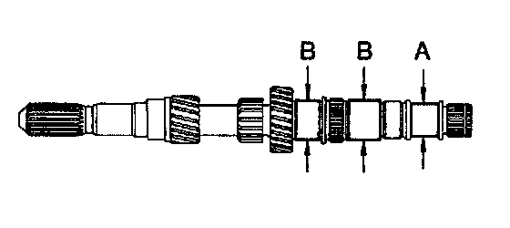
b. Using a micrometer, measure the outer diameter of the input shaft journal surface.
Minimum outer diameter:
Part A: 27.950 mm (1.1004 inch)
Part B: 35.950 mm (1.4154 inch)
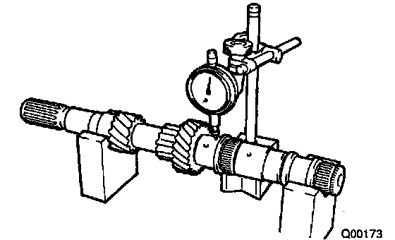
c. Using a dial indicator, check the shaft runout.
Maximum runout: 0.05 mm (0.0020 inch)
REASSEMBLY
HINT: Coat all of the sliding and rotating surfaces with gear oil before reassembly.
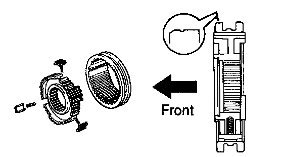
1. INSTALL NO.2 CLUTCH HUB INTO HUB SLEEVE
a. Install the 3 springs and shifting keys to the clutch hub.
b. Install the hub sleeve to the clutch hub.
HINT: Direct identification groove of the hub sleeve to front of the transmission.
2. INSTALL NEEDLE ROLLER BEARING, 3RD GEAR, SYNCHRONIZER RING AND NO.2 HUB SLEEVE ASSEMBLY TO INPUT SHAFT
a. Apply MP grease to the needle roller bearing.
b. Assemble the needle roller bearings into the 3rd gear.
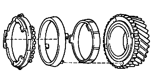
c. Place the synchronizer rings on the gear and align the ring slots with the shifting keys.
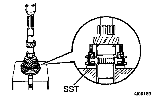
d. Using SST and a press, install the 3rd gear and No.2 hub sleeve.
SST 09506-35010
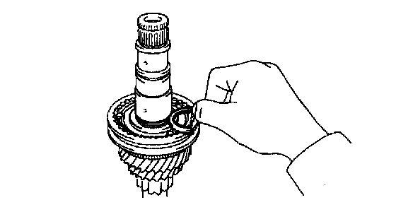
3. INSTALL SNAP RING
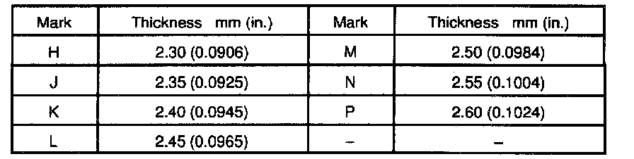
a. Select a snap ring that allows the minimum axial play.
b. Using a screwdriver and hammer, tap in the snap ring.
4. MEASURE 3RD GEAR THRUST CLEARANCE
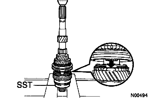
5. INSTALL SPACER, SYNCHRONIZER RING, NEEDLE ROLLER BEARING, 4TH GEAR AND REAR BALL BEARING
a. Install the spacer.
b. Apply MP grease to the needle roller bearings.
c. Place the synchronizer ring on the gear and align the ring slots with the shifting keys.
d. Install the 4th gear.
e. Using SST and a press, install the rear ball bearing.
SST 09506-35010
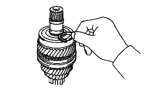
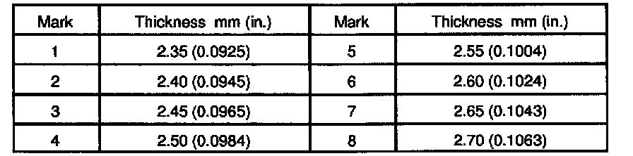
6. INSTALL SNAP RING
a. Select a snap ring that allows the minimum axial play.
b. Using a screwdriver and hammer, tap in the snap ring.
7. MEASURE 4TH GEAR THRUST CLEARANCE
Factory Service Tools
Use the Manual With the Right Hardware
Pair factory procedures with proven DIY tools so the instructions are easier to execute.
Disclosure: Verified tool recommendations may earn an affiliate commission at no cost to you.
When to See a Mechanic
Stop DIY work and contact a certified mechanic immediately if any of the following apply:
- • You smell fuel, burning insulation, or see smoke.
- • Brakes feel soft, pull hard to one side, or make grinding noises.
- • The engine overheats, stalls repeatedly, or misfires under load.
- • You are missing required tools, torque specs, or safe lifting equipment.
- • You are not confident in the next step or safety outcome.
Rather have a pro handle this?
A certified mobile mechanic comes to your home or office. They bring the tools, you stay comfortable. No tow truck, no waiting room, no surprises.
Comes to youSame-day available12-month warranty
Get a Free QuoteNo obligation. See pricing before you book.