
Safety Warning
DIY auto repair can cause serious injury, fire, or vehicle damage. These guides are for informational purposes only. Always follow OEM torque specs, wear PPE, and consult a certified mechanic if you are unsure. You are solely responsible for your safety.
2000 Toyota RAV4 2-Door 2WD L4-2.0L (3S-FE)FACTORY OEM SERVICE PROCEDURE
Part 2
42. CHECK PACK CLEARANCE OF 1ST & REVERSE BRAKE
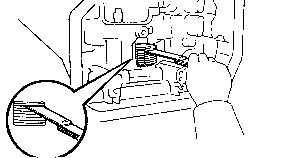
Using a feeler gauge, measure the 1st & reverse brake pack clearance.
Pack clearance (reference): 1.19 - 2.25 mm (0.0469 - 0.0886 inch.)
If the pack clearance is non-standard, check the disc.
43. REMOVE 1ST & REVERSE BRAKE PACK
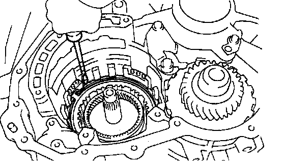
a. Using a screwdriver, remove the snap ring.
HINT: Tape the screwdriver tip before use.
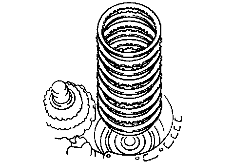
b. Remove the flange, plates and discs.
44. REMOVE TRANSAXLE REAR CASE
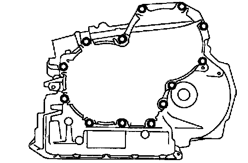
a. Remove the 13 bolts.
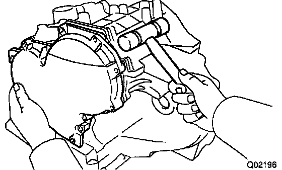
b. Tap off the circumference of the cover with a plastic hammer to remove the rear case from the transaxle case, and remove the cover.
45. REMOVE INTERMEDIATE SHAFT
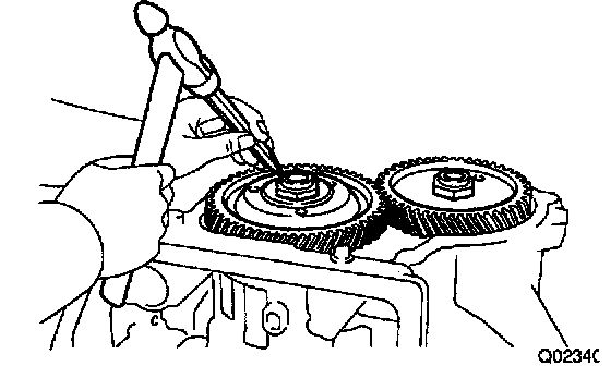
a. Using a chisel and hammer, unstake the intermediate shaft lock nut.
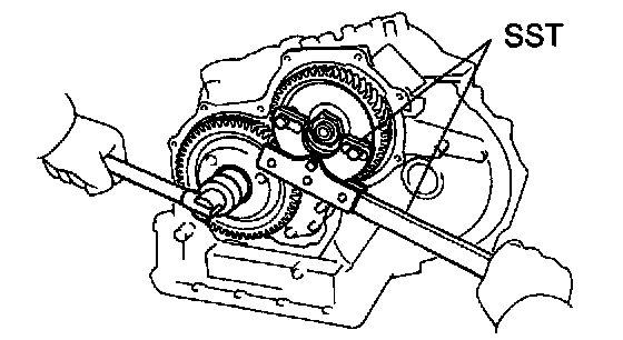
b. Using SST, remove the lock nut.
SST 09330 - 00021,09350 - 32014(09351 - 32032)
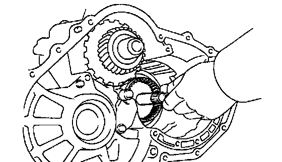
c. Remove the intermediate shaft.
46. REMOVE COUNTER DRIVE GEAR
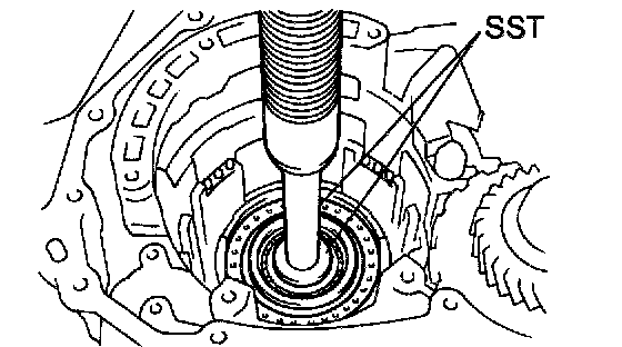
a. Using SST and a press, remove the counter drive gear.
SST 09950 - 60010 (09951 - 00380), 09950 - 70010 (09950 - 07100)
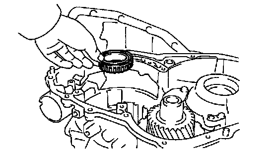
47. REMOVE FRONT BEARING
48. REMOVE COUNTER DRIVEN GEAR
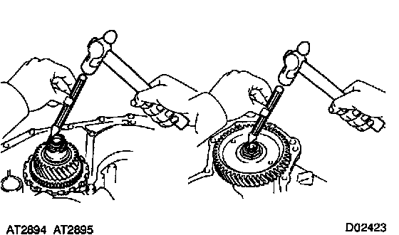
a. Using a chisel and hammer, unstake the counter shaft lock nut on both sides.
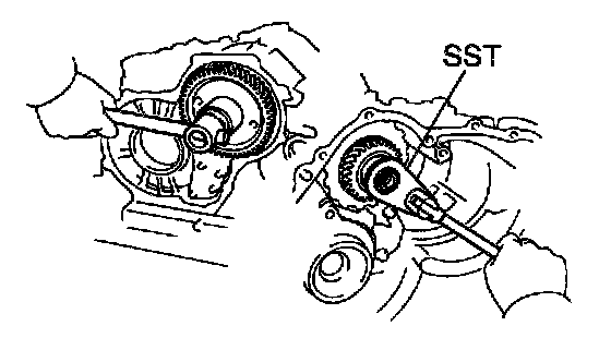
b. Using SST to hold the counter shaft, remove the lock nut of the driven gear side.
SST 09350 - 32014 (09351 - 32170)
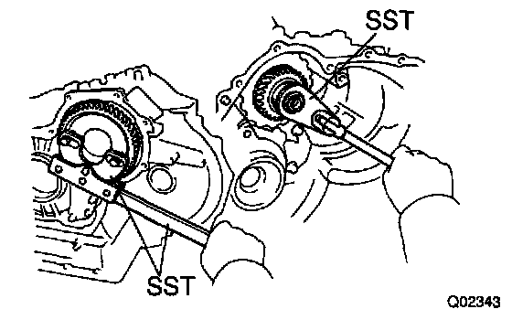
c. Using SST to hold the driven gear, remove the lock nut of the another side.
SST 09930 - 00021, 09350 - 32014 (09351 - 32032, 09351 - 32170)
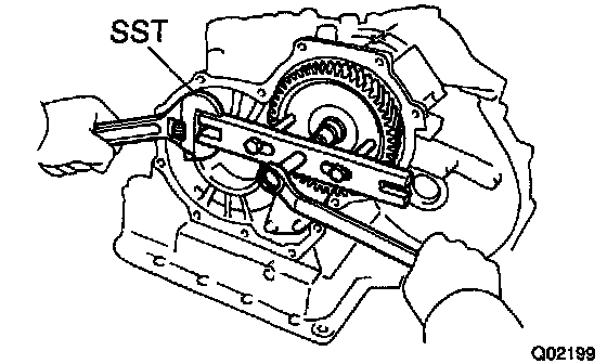
d. Using SST, remove the driven gear. SST 09350-32014 (09351 - 32061)

e. Remove the thrust needle bearing.
49. REMOVE COUNTER SHAFT ASSEMBLY
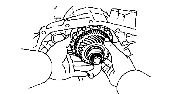
a. Pull out the counter shaft assembly.
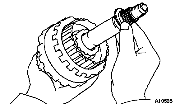
b. Remove the thrust bearing with race from the counter shaft assembly.
50. CHECK PISTON STROKE OF U/D CLUTCH
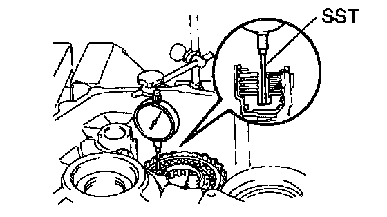
a. Set a dial indicator (long type pick or SST).
SST 09350 - 32014 (09351 - 32190)
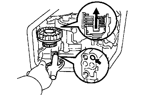
b. While applying and releasing compressed air (392 - 785 kPa, 4 - 8 kgf/cm2, 57 -114 psi), measure the U/D clutch piston stroke.
Piston stroke: 1.50 - 1.90 mm (0.0590 - 0.0748 inch.)
If the piston stroke is non-standard, select another flange.
HINT: There are 4 different flange thicknesses.
Flange thickness:
2.04 mm (0.0803 inch.)
2.20 mm (0.0866 inch.)
2.40 mm (0.0945 inch.)
2.50 mm (0.0984 inch.)
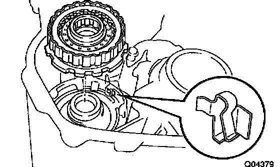
51. REMOVE U/D CLUTCH DRUM AND ANTIRATTLE CLIP
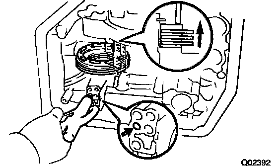
52. CHECK PACK CLEARANCE OF U/D BRAKE
Using a dial indicator, measure the U/D brake pack clearance.
Pack clearance (reference): 1.15 - 1.97 mm (0.0453 - 0.0776 inch.)
If clearance is non-standard, check the disc.
53. REMOVE U/D BRAKE
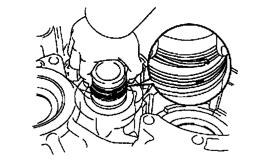
a. Remove the 2 oil seal rings.
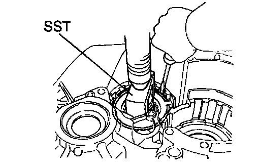
b. Using SST and a press, press inch the flange until the snap ring is free from the flange.
SST 09350 - 32014 (09351 - 32070)
c. Using a screwdriver, remove the snap ring.
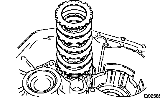
d. Remove the flange, 3 plates and disc.
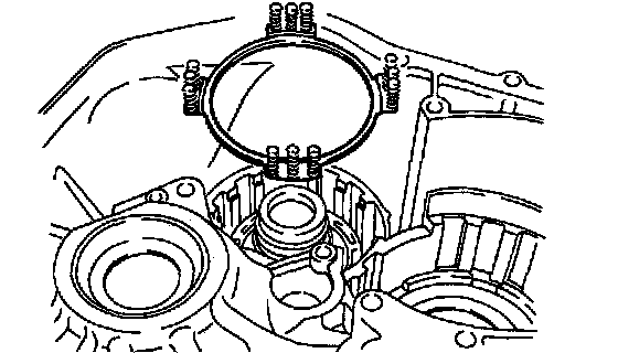
e. Remove the piston return spring.
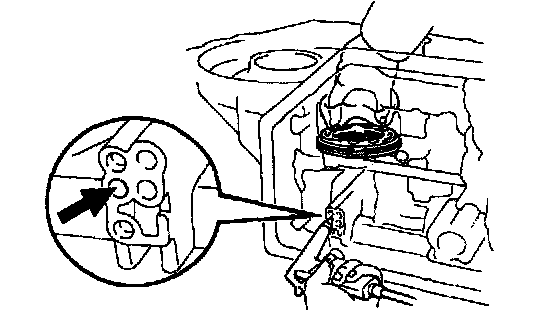
f. Using low-pressure compressed air (98 kPa, 1 kgf/cm2, 14 psi), pop out the brake piston into a rag.
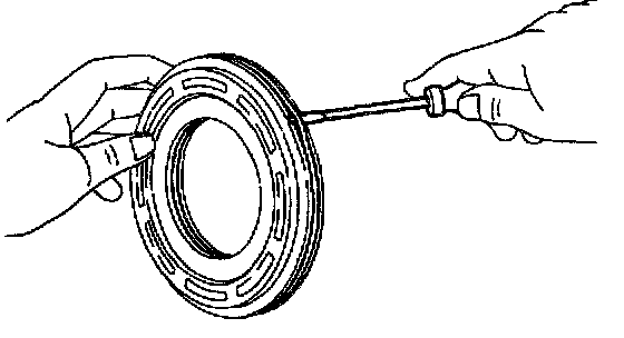
g. Using a screwdriver, remove the 2 O-rings from the piston.
54. REMOVE 1ST & REVERSE BRAKE PISTON
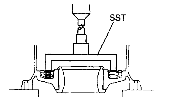
a. Using SST and a press, press inch the return spring until the snap ring is free from the return spring.
b. Using snap ring pliers, remove the snap ring.
SST 09350 - 32014(09351 - 32040)

c. Remove the return spring and snap ring.
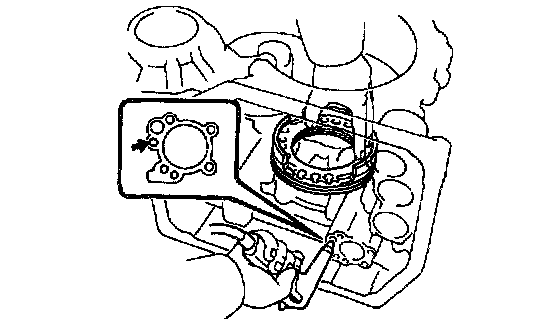
d. Apply compressed air into the oil passage of the case to remove the piston.
HINT: Hold the piston so it is not slanted and blow with the gun slightly away from the oil hole.
e. If the piston does not pop out with compressed air, use needle-nose pliers to remove it.
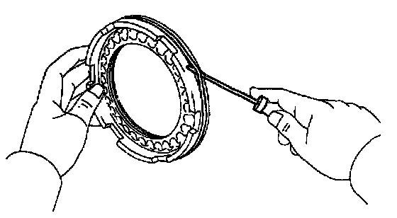
f. Using a screwdriver, remove the 2 O-rings from the piston.
55. REMOVE PARKING LOCK PAWL
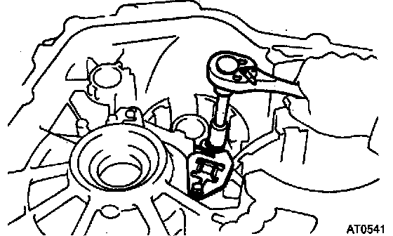
a. Remove the 2 bolts, parking lock pawl stopper plate, torsion spring and spring guide.
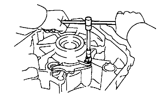
b. Remove the bolt and pawl shaft clamp.

c. Remove the parking lock pawl shaft and lock pawl.
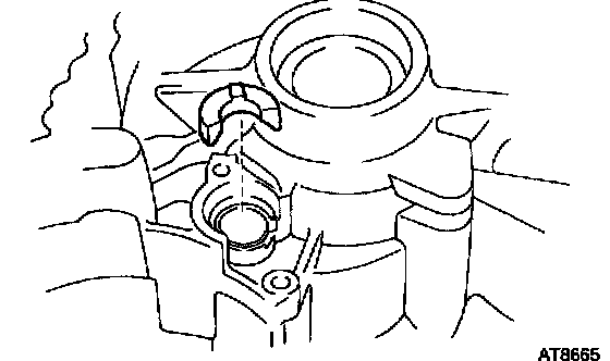
56. REMOVE PARKING LOCK SLEEVE
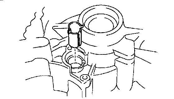
57. REMOVE CAM GUIDE BRACKET
Remove the cam guide bracket.
58. REMOVE B4 ACCUMULATOR PISTON AND SPRING

a. Remove the 3 bolts.
b. Using a torx wrench, remove the 6 screws.
Remove the gallery cover and gasket.
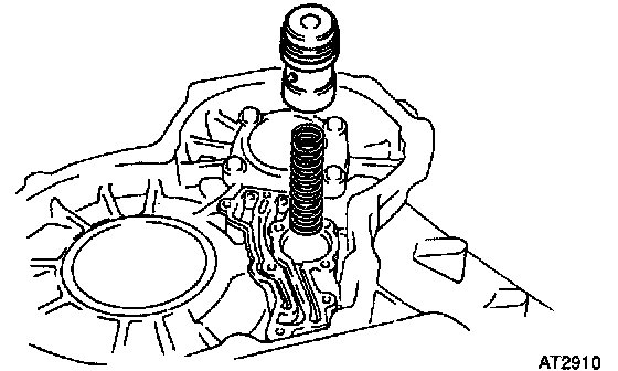
c. Remove the B4 accumulator piston and spring.
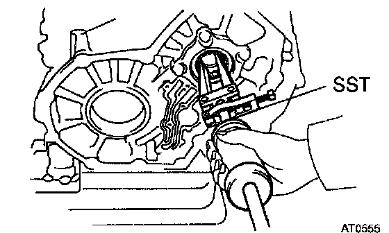
59. REMOVE BEARING
Using SST, remove the bearing.
SST 09308 - 00010
60. REMOVE OIL PIPE
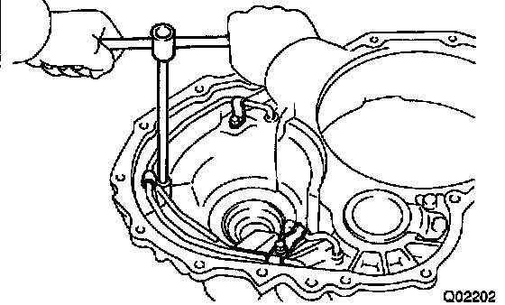
a. Remove the 3 bolts and oil pipe clamps.
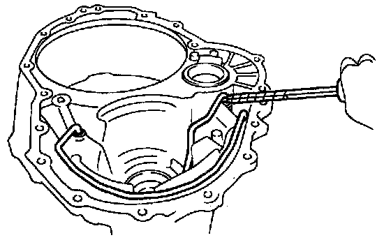
b. Using a screwdriver, remove the 2 oil pipes.
HINT: Tape the screwdriver tip before use.
NOTICE: Be careful not to bend or damage the pipes.
61. REMOVE BEARING
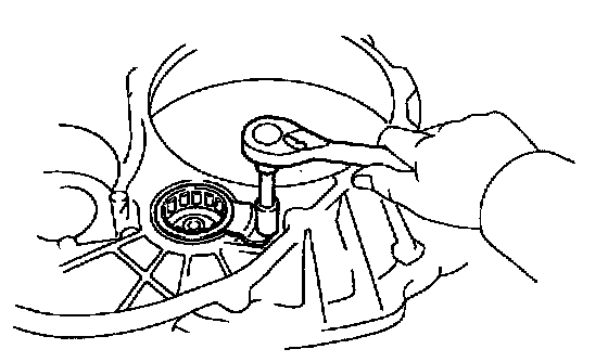
a. Remove the bolt and retainer.
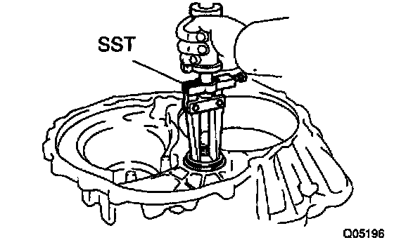
b. Using SST, remove the bearing.
SST 09308 - 00010
Using a feeler gauge, measure the 1st & reverse brake pack clearance.
Pack clearance (reference): 1.19 - 2.25 mm (0.0469 - 0.0886 inch.)
If the pack clearance is non-standard, check the disc.
43. REMOVE 1ST & REVERSE BRAKE PACK
a. Using a screwdriver, remove the snap ring.
HINT: Tape the screwdriver tip before use.
b. Remove the flange, plates and discs.
44. REMOVE TRANSAXLE REAR CASE
a. Remove the 13 bolts.
b. Tap off the circumference of the cover with a plastic hammer to remove the rear case from the transaxle case, and remove the cover.
45. REMOVE INTERMEDIATE SHAFT
a. Using a chisel and hammer, unstake the intermediate shaft lock nut.
b. Using SST, remove the lock nut.
SST 09330 - 00021,09350 - 32014(09351 - 32032)
c. Remove the intermediate shaft.
46. REMOVE COUNTER DRIVE GEAR
a. Using SST and a press, remove the counter drive gear.
SST 09950 - 60010 (09951 - 00380), 09950 - 70010 (09950 - 07100)
47. REMOVE FRONT BEARING
48. REMOVE COUNTER DRIVEN GEAR
a. Using a chisel and hammer, unstake the counter shaft lock nut on both sides.
b. Using SST to hold the counter shaft, remove the lock nut of the driven gear side.
SST 09350 - 32014 (09351 - 32170)
c. Using SST to hold the driven gear, remove the lock nut of the another side.
SST 09930 - 00021, 09350 - 32014 (09351 - 32032, 09351 - 32170)
d. Using SST, remove the driven gear. SST 09350-32014 (09351 - 32061)
e. Remove the thrust needle bearing.
49. REMOVE COUNTER SHAFT ASSEMBLY
a. Pull out the counter shaft assembly.
b. Remove the thrust bearing with race from the counter shaft assembly.
50. CHECK PISTON STROKE OF U/D CLUTCH
a. Set a dial indicator (long type pick or SST).
SST 09350 - 32014 (09351 - 32190)
b. While applying and releasing compressed air (392 - 785 kPa, 4 - 8 kgf/cm2, 57 -114 psi), measure the U/D clutch piston stroke.
Piston stroke: 1.50 - 1.90 mm (0.0590 - 0.0748 inch.)
If the piston stroke is non-standard, select another flange.
HINT: There are 4 different flange thicknesses.
Flange thickness:
2.04 mm (0.0803 inch.)
2.20 mm (0.0866 inch.)
2.40 mm (0.0945 inch.)
2.50 mm (0.0984 inch.)
51. REMOVE U/D CLUTCH DRUM AND ANTIRATTLE CLIP
52. CHECK PACK CLEARANCE OF U/D BRAKE
Using a dial indicator, measure the U/D brake pack clearance.
Pack clearance (reference): 1.15 - 1.97 mm (0.0453 - 0.0776 inch.)
If clearance is non-standard, check the disc.
53. REMOVE U/D BRAKE
a. Remove the 2 oil seal rings.
b. Using SST and a press, press inch the flange until the snap ring is free from the flange.
SST 09350 - 32014 (09351 - 32070)
c. Using a screwdriver, remove the snap ring.
d. Remove the flange, 3 plates and disc.
e. Remove the piston return spring.
f. Using low-pressure compressed air (98 kPa, 1 kgf/cm2, 14 psi), pop out the brake piston into a rag.
g. Using a screwdriver, remove the 2 O-rings from the piston.
54. REMOVE 1ST & REVERSE BRAKE PISTON
a. Using SST and a press, press inch the return spring until the snap ring is free from the return spring.
b. Using snap ring pliers, remove the snap ring.
SST 09350 - 32014(09351 - 32040)
c. Remove the return spring and snap ring.
d. Apply compressed air into the oil passage of the case to remove the piston.
HINT: Hold the piston so it is not slanted and blow with the gun slightly away from the oil hole.
e. If the piston does not pop out with compressed air, use needle-nose pliers to remove it.
f. Using a screwdriver, remove the 2 O-rings from the piston.
55. REMOVE PARKING LOCK PAWL
a. Remove the 2 bolts, parking lock pawl stopper plate, torsion spring and spring guide.
b. Remove the bolt and pawl shaft clamp.
c. Remove the parking lock pawl shaft and lock pawl.
56. REMOVE PARKING LOCK SLEEVE
57. REMOVE CAM GUIDE BRACKET
Remove the cam guide bracket.
58. REMOVE B4 ACCUMULATOR PISTON AND SPRING
a. Remove the 3 bolts.
b. Using a torx wrench, remove the 6 screws.
Remove the gallery cover and gasket.
c. Remove the B4 accumulator piston and spring.
59. REMOVE BEARING
Using SST, remove the bearing.
SST 09308 - 00010
60. REMOVE OIL PIPE
a. Remove the 3 bolts and oil pipe clamps.
b. Using a screwdriver, remove the 2 oil pipes.
HINT: Tape the screwdriver tip before use.
NOTICE: Be careful not to bend or damage the pipes.
61. REMOVE BEARING
a. Remove the bolt and retainer.
b. Using SST, remove the bearing.
SST 09308 - 00010
Factory Service Tools
Use the Manual With the Right Hardware
Pair factory procedures with proven DIY tools so the instructions are easier to execute.
Disclosure: Verified tool recommendations may earn an affiliate commission at no cost to you.
When to See a Mechanic
Stop DIY work and contact a certified mechanic immediately if any of the following apply:
- • You smell fuel, burning insulation, or see smoke.
- • Brakes feel soft, pull hard to one side, or make grinding noises.
- • The engine overheats, stalls repeatedly, or misfires under load.
- • You are missing required tools, torque specs, or safe lifting equipment.
- • You are not confident in the next step or safety outcome.
Rather have a pro handle this?
A certified mobile mechanic comes to your home or office. They bring the tools, you stay comfortable. No tow truck, no waiting room, no surprises.
Comes to youSame-day available12-month warranty
Get a Free QuoteNo obligation. See pricing before you book.