
Safety Warning
DIY auto repair can cause serious injury, fire, or vehicle damage. These guides are for informational purposes only. Always follow OEM torque specs, wear PPE, and consult a certified mechanic if you are unsure. You are solely responsible for your safety.
2000 Toyota RAV4 2-Door 2WD L4-2.0L (3S-FE)FACTORY OEM SERVICE PROCEDURE
Automatic Transaxle Replacement
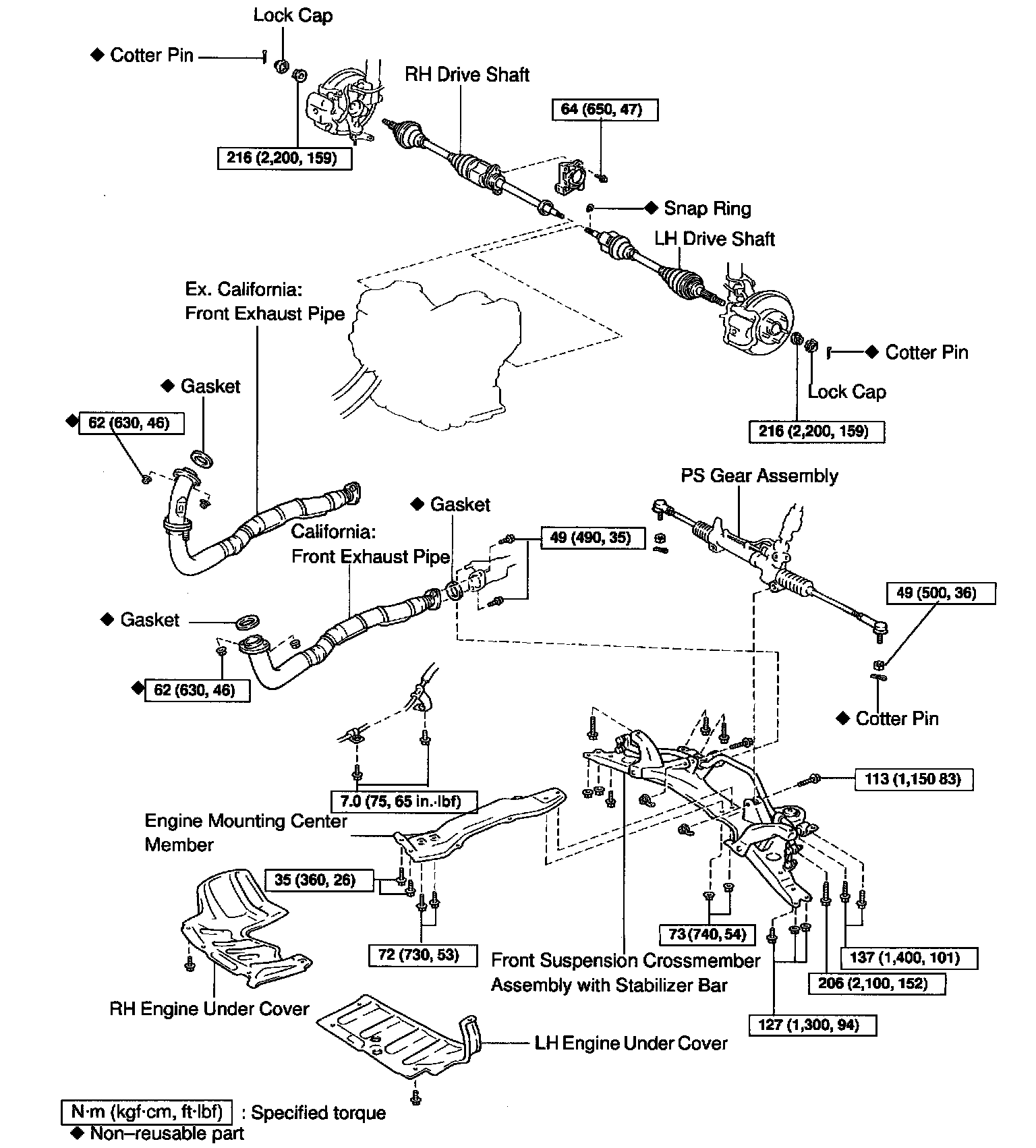

REMOVAL
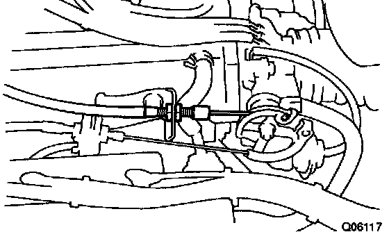
1. DISCONNECT THROTTLE CABLE
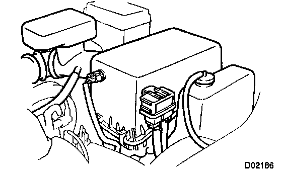
2. REMOVE ENGINE COOLANT RESERVOIR TANK
3. REMOVE AIR CLEANER ASSEMBLY
a. Disconnect the connector and ABS relay.
b. Remove the 3 bolts and air cleaner assembly.
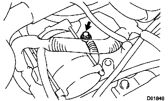
4. REMOVE GROUND CABLE
Remove the bolt from the transaxle.
Torque: 19 Nm (194 kgf-cm, 14 ft. lbs.)

5. REMOVE SET NUT OF ENGINE WIRE CLAMP
6. REMOVE STARTER

a. Disconnect the connector and nut from the starter.
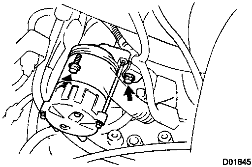
b. Remove the 2 bolts and disconnect the engine wire.
Torque: 39 Nm (400 kgf-cm, 29 ft. lbs.)
c. Remove the starter.
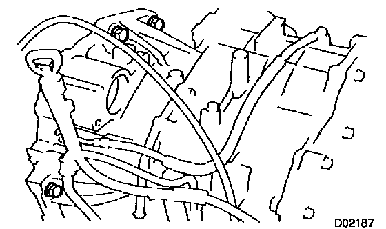
7. REMOVE 3 UPPER SIDE TRANSAXLE MOUNTING BOLTS
Torque: 64 Nm (650 kgf-cm, 47 ft. lbs.)
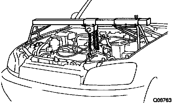
8. INSTALL ENGINE SUPPORT FIXTURE
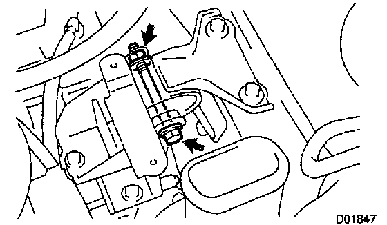
9. REMOVE ENGINE LEFT MOUNTING BOLT AND NUT
Torque: 64 Nm (650 kgf-cm, 47 ft. lbs.)
10. REMOVE LEFT AND RIGHT ENGINE UNDER COVERS
11. DRAIN ATF
12. REMOVE LEFT AND RIGHT DRIVE SHAFTS. Refer to Steering and Suspension.
13. REMOVE FRONT EXHAUST PIPE
a. Remove the 2 bolts and gasket from the exhaust pipe.
Torque: 48 Nm (490 kgf-cm, 35 ft. lbs.)
HINT: At the time of installation, please refer to the following item. Replace used gasket with new gasket.
b. Remove the 3 nuts, front exhaust pipe and gasket.
Torque: 62 Nm (630 kgf-cm, 46 ft. lbs.)
HINT: At the time of installation, please refer to the following item. Replace used nuts and gasket with new nuts and gasket.
14. DISCONNECT SHIFT CONTROL CABLE
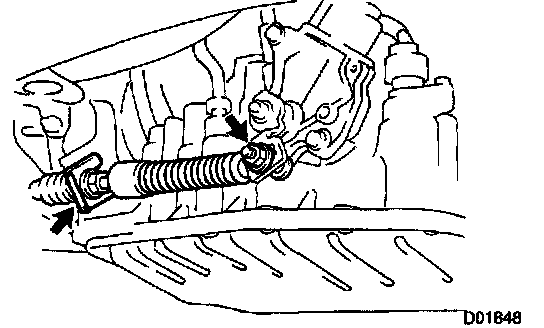
a. Remove the nut from the control shaft lever.
Torque: 13 Nm (135 kgf-cm, 10 ft. lbs.)
b. Remove the clip and disconnect the control cable.

c. Remove the 2 shift cable mounting bolts.
Torque: 7.0 Nm (75 kgf-cm, 65 inch lbs.)
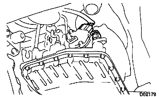
15. DISCONNECT FOLLOWING CONNECTORS
- Shift solenoid valve SL connector
- Park/neutral position switch connector
- Vehicle speed sensor connector

16. DISCONNECT OIL COOLER HOSE
Loosen the 2 clips and disconnect the 2 oil cooler hoses.
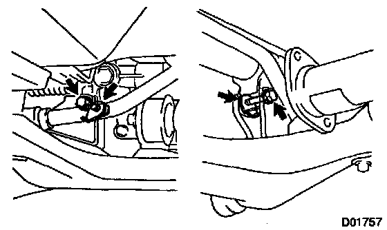
17. REMOVE 2 POWER STEERING GEAR MOUNTING BOLTS AND NUTS
Torque: 113 Nm (1,150 kgf-cm, 83 ft. lbs.)
NOTICE: Support the power steering gear housing securely.

18. REMOVE FRONT SUSPENSION CROSSMEMBER ASSEMBLY WITH STABILIZER BAR
Remove the 10 bolts, 2 nuts and front suspension crossmember assembly with stabilizer bar.
Torque:
A bolt: 206 Nm (2,100 kgf-cm, 152 ft. lbs.)
B bolt: 137 Nm (1,400 kgf-cm, 101 ft. lbs.)
C bolt: 35 Nm (360 kgf-cm, 26 ft. lbs.)
D bolt: 72 Nm (730 kgf-cm, 53 ft. lbs.)
Nut: 73 Nm (740 kgf-cm, 54 ft. lbs.)
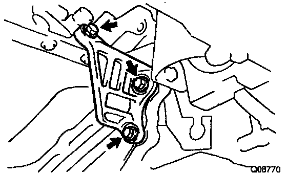
19. REMOVE STIFFENER PLATE
Remove the 3 bolts and stiffener plate.
Torque: 37 Nm (380 kgf-cm, 27 ft. lbs.)

20. REMOVE REAR END PLATE
Remove the 4 bolts and rear end plate.
Torque:
A bolt: 9.0 Nm (95 kgf-cm, 78 inch lbs.)
B bolt: 25 Nm (250 kgf-cm, 18 ft. lbs.)

21. REMOVE TORQUE CONVERTER CLUTCH MOUNTING BOLT
Turn the crankshaft to gain access and remove the 6 bolts with holding the crankshaft pulley set bolt by a wrench.
Torque: 27 Nm (280 kgf-cm, 20 ft. lbs.)
HINT: At the time of installation, please refer to the following item. First install the gray bolt. Then install 5 black bolts while turning the crankshaft to grain access.
22. SUPPORT TRANSAXLE WITH A TRANSMISSION JACK

23. REMOVE TRANSAXLE
Remove the rear side transaxle mounting 2 bolts and transaxle.
Torque:
A bolt: 25 Nm (250 kgf-cm, 18 ft. lbs.)
B bolt: 46 Nm (470 kgf-cm, 34 ft. lbs.)
INSTALLATION
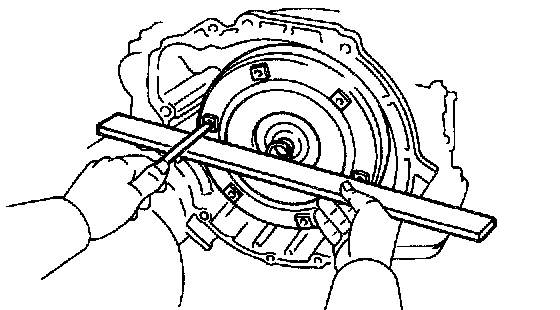
1. INSTALL TORQUE CONVERTER CLUTCH
Using calipers and a straight edge, measure from the installed surface to front surface of the transaxle housing.
Correct distance: More than 12.75 mm (0.502 inch)
2. INSTALL TRANSAXLE
Installation is in the reverse order of removal.
HINT: After installation, check and inspect items as follows.
- Fluid level
- Front wheel alignment. Refer to Steering and Suspension.
- Road test the vehicle
Factory Service Tools
Use the Manual With the Right Hardware
Pair factory procedures with proven DIY tools so the instructions are easier to execute.
Disclosure: Verified tool recommendations may earn an affiliate commission at no cost to you.
When to See a Mechanic
Stop DIY work and contact a certified mechanic immediately if any of the following apply:
- • You smell fuel, burning insulation, or see smoke.
- • Brakes feel soft, pull hard to one side, or make grinding noises.
- • The engine overheats, stalls repeatedly, or misfires under load.
- • You are missing required tools, torque specs, or safe lifting equipment.
- • You are not confident in the next step or safety outcome.
Rather have a pro handle this?
A certified mobile mechanic comes to your home or office. They bring the tools, you stay comfortable. No tow truck, no waiting room, no surprises.
Comes to youSame-day available12-month warranty
Get a Free QuoteNo obligation. See pricing before you book.