
Safety Warning
DIY auto repair can cause serious injury, fire, or vehicle damage. These guides are for informational purposes only. Always follow OEM torque specs, wear PPE, and consult a certified mechanic if you are unsure. You are solely responsible for your safety.
2000 Toyota RAV4 2-Door 2WD L4-2.0L (3S-FE)FACTORY OEM SERVICE PROCEDURE
Camshaft Bearing Torque and Sequence
INSTALL INTAKE CAMSHAFTS
NOTICE: Since the thrust clearance of the camshaft is small, the camshaft must be kept level while it is being installed. If the camshaft is not kept level, the portion of the cylinder head receiving the shaft thrust may crack or be damaged, causing the camshaft to seize or break. To avoid this, the following steps should be carried out.
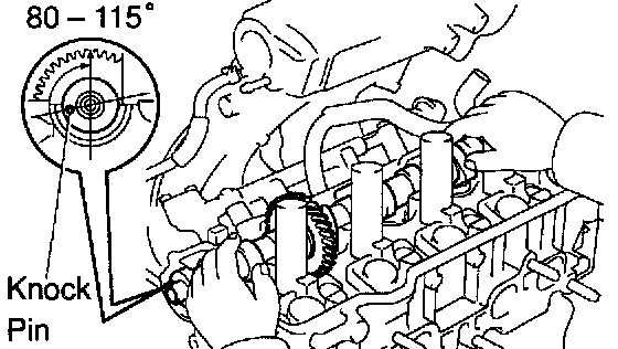
a. Apply MP grease to the thrust portion of the camshaft.
b. Place the intake camshaft at 8 - 115° BTDC of camshaft angle on the cylinder head.
HINT: The above angle arrows the No. 1 and No. 3 cylinder cam lobes of the intake camshaft to push their valve lifters evenly.
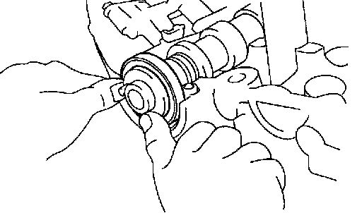
c. Apply MP grease to a new oil seal lip.
d. Install the oil seal as far as the deepest part of the cylinder head.
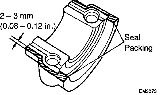
e. Apply seal packing to the No. 1 bearing cap as shown.
Seal packing: Part No.0882-00080 or equivalent

f. Install the bearing caps in their proper locations.
g. Apply a light coat of engine oil on the threads and under the heads of the bearing cap bolts.
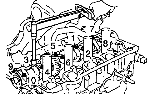
h. Install and uniformly tighten the 10 bearing cap bolts, in several passes, in the sequence shown.
Torque: 19 Nm (190 kgf-cm, 14 ft. lbs.)
INSTALL EXHAUST CAMSHAFT
NOTICE: Since the thrust clearance of the camshaft is small, the camshaft must be kept level while it is being installed. If the camshaft is not kept level, the portion of the cylinder head receiving the shaft thrust may crack or be damaged, causing the camshaft to seize or break. To avoid this, the following steps should be carried out.

a. Set the knock pin of the intake camshaft at 10 - 45° BTDC of camshaft angle.
HINT: The above angle allows the No. 2 and No. 4 cylinder cam lobes of the exhaust camshaft to push their valve lifters evenly.
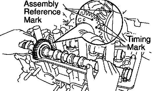
b. Apply MP grease to the thrust portion of the camshaft.
c. Engage the exhaust camshaft gear to the intake camshaft gear by matching the timing marks on each gear.
d. Roll down the exhaust camshaft onto the bearing journals while engaging gears with each other.
NOTICE: There are also assembly reference marks on each gear as shown in the illustration. Do not use these marks.
e. Turn the intake camshaft clockwise or counterclockwise a little untie the exhaust camshaft sits in the bearing journals evenly without rocking the camshaft on the bearing journals.
NOTICE: It is very important to replace the camshaft in the bearing journals evenly while tightening bearing caps in the subsequent steps.

f. Install the bearing caps in their proper locations.
g. Apply a light coat of engine oil on the threads and under the heads of the bearing cap bolts.

h. Install and uniformly tighten the 10 bearing cap bolts, in several passes, in the sequence shown.
Torque: 19 Nm (190 kgf-cm, 14 ft. lbs.)
i. Remove the service bolt B.
NOTICE: Since the thrust clearance of the camshaft is small, the camshaft must be kept level while it is being installed. If the camshaft is not kept level, the portion of the cylinder head receiving the shaft thrust may crack or be damaged, causing the camshaft to seize or break. To avoid this, the following steps should be carried out.
a. Apply MP grease to the thrust portion of the camshaft.
b. Place the intake camshaft at 8 - 115° BTDC of camshaft angle on the cylinder head.
HINT: The above angle arrows the No. 1 and No. 3 cylinder cam lobes of the intake camshaft to push their valve lifters evenly.
c. Apply MP grease to a new oil seal lip.
d. Install the oil seal as far as the deepest part of the cylinder head.
e. Apply seal packing to the No. 1 bearing cap as shown.
Seal packing: Part No.0882-00080 or equivalent
f. Install the bearing caps in their proper locations.
g. Apply a light coat of engine oil on the threads and under the heads of the bearing cap bolts.
h. Install and uniformly tighten the 10 bearing cap bolts, in several passes, in the sequence shown.
Torque: 19 Nm (190 kgf-cm, 14 ft. lbs.)
INSTALL EXHAUST CAMSHAFT
NOTICE: Since the thrust clearance of the camshaft is small, the camshaft must be kept level while it is being installed. If the camshaft is not kept level, the portion of the cylinder head receiving the shaft thrust may crack or be damaged, causing the camshaft to seize or break. To avoid this, the following steps should be carried out.
a. Set the knock pin of the intake camshaft at 10 - 45° BTDC of camshaft angle.
HINT: The above angle allows the No. 2 and No. 4 cylinder cam lobes of the exhaust camshaft to push their valve lifters evenly.
b. Apply MP grease to the thrust portion of the camshaft.
c. Engage the exhaust camshaft gear to the intake camshaft gear by matching the timing marks on each gear.
d. Roll down the exhaust camshaft onto the bearing journals while engaging gears with each other.
NOTICE: There are also assembly reference marks on each gear as shown in the illustration. Do not use these marks.
e. Turn the intake camshaft clockwise or counterclockwise a little untie the exhaust camshaft sits in the bearing journals evenly without rocking the camshaft on the bearing journals.
NOTICE: It is very important to replace the camshaft in the bearing journals evenly while tightening bearing caps in the subsequent steps.
f. Install the bearing caps in their proper locations.
g. Apply a light coat of engine oil on the threads and under the heads of the bearing cap bolts.
h. Install and uniformly tighten the 10 bearing cap bolts, in several passes, in the sequence shown.
Torque: 19 Nm (190 kgf-cm, 14 ft. lbs.)
i. Remove the service bolt B.
Factory Service Tools
Use the Manual With the Right Hardware
Pair factory procedures with proven DIY tools so the instructions are easier to execute.
Disclosure: Verified tool recommendations may earn an affiliate commission at no cost to you.
When to See a Mechanic
Stop DIY work and contact a certified mechanic immediately if any of the following apply:
- • You smell fuel, burning insulation, or see smoke.
- • Brakes feel soft, pull hard to one side, or make grinding noises.
- • The engine overheats, stalls repeatedly, or misfires under load.
- • You are missing required tools, torque specs, or safe lifting equipment.
- • You are not confident in the next step or safety outcome.
Rather have a pro handle this?
A certified mobile mechanic comes to your home or office. They bring the tools, you stay comfortable. No tow truck, no waiting room, no surprises.
Comes to youSame-day available12-month warranty
Get a Free QuoteNo obligation. See pricing before you book.