
Safety Warning
DIY auto repair can cause serious injury, fire, or vehicle damage. These guides are for informational purposes only. Always follow OEM torque specs, wear PPE, and consult a certified mechanic if you are unsure. You are solely responsible for your safety.
2000 Toyota RAV4 2-Door 2WD L4-2.0L (3S-FE)FACTORY OEM SERVICE PROCEDURE
Fuel System
1. BEFORE WORKING ON FUEL SYSTEM, DISCONNECT NEGATIVE (-) TERMINAL CABLE FROM BATTERY
HINT: Any diagnostic trouble code retained by the computer will be erased when the negative (-) terminal cable is removed from the battery. Therefore, if necessary, read the diagnosis before removing the negative (-) terminal cable from the battery.
2. DO NOT SMOKE OR WORK NEAR AN OPEN FLAME WHEN WORKING ON FUEL SYSTEM
3. KEEP GASOLINE AWAY FROM RUBBER OR LEATHER PARTS
4. FUEL SYSTEM
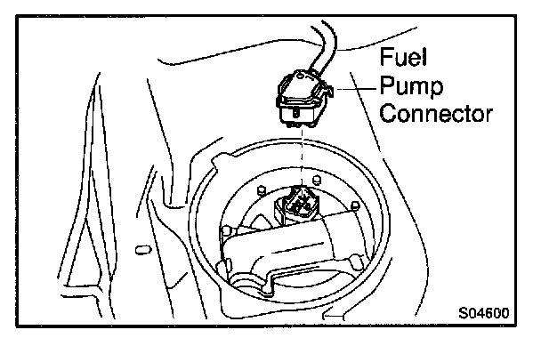
A. When disconnecting the high fuel pressure line, a large amount of gasoline will spill out, so observe the following procedures:
1. Disconnect the fuel pump connector.
2. Start the engine. After the engine has stopped on its own, turn the ignition switch to LOCK.
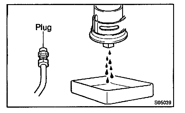
3. Put a container under the connection.
4. Slowly loosen the connection.
5. Disconnect the connection.
6. Plug the connection with a rubber plug.
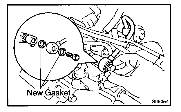
B. When connecting the union bolt on the high pressure pipe union, observe the following procedures:
1. Always use 2 new gaskets.
2. Tighten the union bolt by hand.
3. Tighten the union bolt to the specified torque.
Torque: 29 Nm (300 kg.cm, 21 ft.lb)

C. When connecting the flare nut on the high pressure pipe union, observe the following procedures:
1. Apply a light coat of engine oil to the flare nut, and tighten the flare nut by hand.
2. Using SST, tighten the flare nut to specified torque.
SST 09631-22020
NOTE: Do not rotate the fuel pipe, when tightening the flare nut.
Torque: 28 Nm (285 kg.cm, 21 ft.lb)
HINT: Use a torque wrench with a fulcrum length of 30 cm (11.81 in.).

D. Observe the following precautions when removing and installing the injectors.
1. Never reuse the O-ring.
2. When placing a new O-ring on the injector, take care not to damage it in any way.
3. Coat a new O-ring with spindle oil or gasoline before installing-never use engine, gear or brake oil.
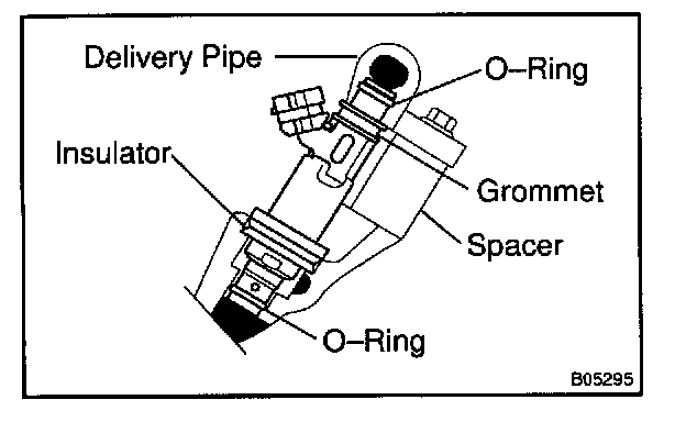
E. Install the injector to the delivery pipe and intake manifold as shown in the illustration.
F. Observe these precautions when disconnecting the fuel tube connector (quick type).
1. Check if there is any dirt like mud on the pipe and around the connector before disconnecting them and clean the dint away.
2. Be sure to disconnect with hands.

3. When the connector and the pipe are stuck, pinch the retainer between the hands, push and pull the connector to free to disconnect and pull it out. Do not use any tool at this time.
4. Inspect if there is any dirt or the likes on the seal surface of the disconnected pipe and clean it away.
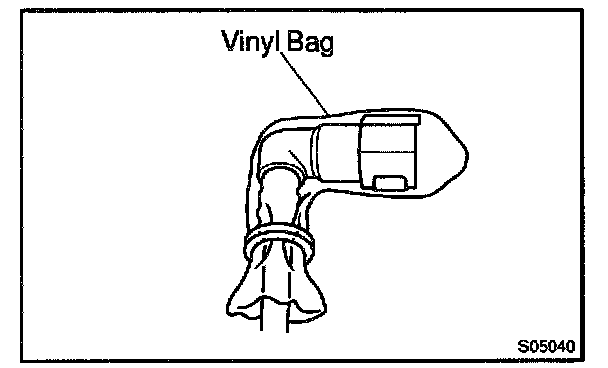
5. Prevent the disconnected pipe and connector from damaging and mixing foreign objects by covering them with a vinyl bag.

G. Observe these precautions when connecting the fuel tube connector (quick type).
1. Do not reuse the retainer removed from the pipe.
2. Must use hands without using tools when to remove the retainer from the pipe.
3. Check if there is any damage or foreign objects on the connected part of the pipe.
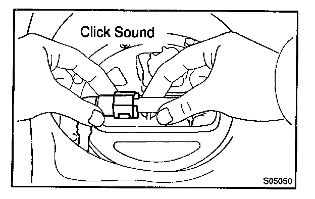
4. Match the axis of the connector with axis of the pipe, and push in the connector until the retainer makes a "click" sound. In case that the connections is tight, apply little amount of new engine oil on the tip of the pipe.
5. After having finished the connection, check if the pipe and the connector are securely connected by pulling them.
6. Check if there is any fuel leakage.
H. Observe these precautions when handling nylon tube.
1. Pay allention not to turn the connector with force when connecting them.
2. Pay attention not to kink the nylon tube.
3. Do not remove the EPDM protector on the outside of the nylon tube.
4. Must not close the piping with the nylon tube by bending it.
Before installing the injector, must apply spindle oil or gasoline on the place where a delivery pipe or an intake manifold touches an O-ring of the injector.
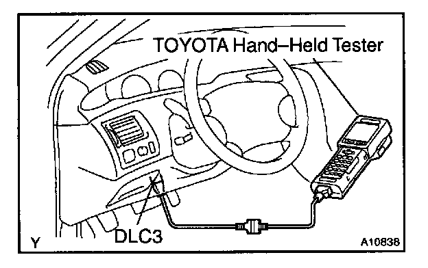
I. Check that there are no fuel leaks after performing maintenance anywhere on the fuel system.
1. Connect a TOYOTA hand-held tester to the DLC3.
2. Turn the ignition switch ON and TOYOTA hand-held tester main switch ON.
NOTE: Do not start the engine.
3. Select the active test mode on the TOYOTA hand- held tester.
4. Please refer to the TOYOTA hand-held tester operator's manual for further details.
5. If you have no TOYOTA hand-held tester, connect the positive (+) and negative (-) leads from the battery to the fuel pump connector.
6. Check that there are no leaks from any pant of the fuel system.
7. Turn the ignition switch to LOCK.
8. Disconnect the TOYOTA hand-held tester from the DLC3.
HINT: Any diagnostic trouble code retained by the computer will be erased when the negative (-) terminal cable is removed from the battery. Therefore, if necessary, read the diagnosis before removing the negative (-) terminal cable from the battery.
2. DO NOT SMOKE OR WORK NEAR AN OPEN FLAME WHEN WORKING ON FUEL SYSTEM
3. KEEP GASOLINE AWAY FROM RUBBER OR LEATHER PARTS
4. FUEL SYSTEM
A. When disconnecting the high fuel pressure line, a large amount of gasoline will spill out, so observe the following procedures:
1. Disconnect the fuel pump connector.
2. Start the engine. After the engine has stopped on its own, turn the ignition switch to LOCK.
3. Put a container under the connection.
4. Slowly loosen the connection.
5. Disconnect the connection.
6. Plug the connection with a rubber plug.
B. When connecting the union bolt on the high pressure pipe union, observe the following procedures:
1. Always use 2 new gaskets.
2. Tighten the union bolt by hand.
3. Tighten the union bolt to the specified torque.
Torque: 29 Nm (300 kg.cm, 21 ft.lb)
C. When connecting the flare nut on the high pressure pipe union, observe the following procedures:
1. Apply a light coat of engine oil to the flare nut, and tighten the flare nut by hand.
2. Using SST, tighten the flare nut to specified torque.
SST 09631-22020
NOTE: Do not rotate the fuel pipe, when tightening the flare nut.
Torque: 28 Nm (285 kg.cm, 21 ft.lb)
HINT: Use a torque wrench with a fulcrum length of 30 cm (11.81 in.).
D. Observe the following precautions when removing and installing the injectors.
1. Never reuse the O-ring.
2. When placing a new O-ring on the injector, take care not to damage it in any way.
3. Coat a new O-ring with spindle oil or gasoline before installing-never use engine, gear or brake oil.
E. Install the injector to the delivery pipe and intake manifold as shown in the illustration.
F. Observe these precautions when disconnecting the fuel tube connector (quick type).
1. Check if there is any dirt like mud on the pipe and around the connector before disconnecting them and clean the dint away.
2. Be sure to disconnect with hands.
3. When the connector and the pipe are stuck, pinch the retainer between the hands, push and pull the connector to free to disconnect and pull it out. Do not use any tool at this time.
4. Inspect if there is any dirt or the likes on the seal surface of the disconnected pipe and clean it away.
5. Prevent the disconnected pipe and connector from damaging and mixing foreign objects by covering them with a vinyl bag.
G. Observe these precautions when connecting the fuel tube connector (quick type).
1. Do not reuse the retainer removed from the pipe.
2. Must use hands without using tools when to remove the retainer from the pipe.
3. Check if there is any damage or foreign objects on the connected part of the pipe.
4. Match the axis of the connector with axis of the pipe, and push in the connector until the retainer makes a "click" sound. In case that the connections is tight, apply little amount of new engine oil on the tip of the pipe.
5. After having finished the connection, check if the pipe and the connector are securely connected by pulling them.
6. Check if there is any fuel leakage.
H. Observe these precautions when handling nylon tube.
1. Pay allention not to turn the connector with force when connecting them.
2. Pay attention not to kink the nylon tube.
3. Do not remove the EPDM protector on the outside of the nylon tube.
4. Must not close the piping with the nylon tube by bending it.
Before installing the injector, must apply spindle oil or gasoline on the place where a delivery pipe or an intake manifold touches an O-ring of the injector.
I. Check that there are no fuel leaks after performing maintenance anywhere on the fuel system.
1. Connect a TOYOTA hand-held tester to the DLC3.
2. Turn the ignition switch ON and TOYOTA hand-held tester main switch ON.
NOTE: Do not start the engine.
3. Select the active test mode on the TOYOTA hand- held tester.
4. Please refer to the TOYOTA hand-held tester operator's manual for further details.
5. If you have no TOYOTA hand-held tester, connect the positive (+) and negative (-) leads from the battery to the fuel pump connector.
6. Check that there are no leaks from any pant of the fuel system.
7. Turn the ignition switch to LOCK.
8. Disconnect the TOYOTA hand-held tester from the DLC3.
Factory Service Tools
Use the Manual With the Right Hardware
Pair factory procedures with proven DIY tools so the instructions are easier to execute.
Disclosure: Verified tool recommendations may earn an affiliate commission at no cost to you.
When to See a Mechanic
Stop DIY work and contact a certified mechanic immediately if any of the following apply:
- • You smell fuel, burning insulation, or see smoke.
- • Brakes feel soft, pull hard to one side, or make grinding noises.
- • The engine overheats, stalls repeatedly, or misfires under load.
- • You are missing required tools, torque specs, or safe lifting equipment.
- • You are not confident in the next step or safety outcome.
Rather have a pro handle this?
A certified mobile mechanic comes to your home or office. They bring the tools, you stay comfortable. No tow truck, no waiting room, no surprises.
Comes to youSame-day available12-month warranty
Get a Free QuoteNo obligation. See pricing before you book.