
Safety Warning
DIY auto repair can cause serious injury, fire, or vehicle damage. These guides are for informational purposes only. Always follow OEM torque specs, wear PPE, and consult a certified mechanic if you are unsure. You are solely responsible for your safety.
2004 GMC Jimmy (CANADA) V6-4.3LFACTORY OEM SERVICE PROCEDURE
Distributor Replacement
DISTRIBUTOR REPLACEMENT
REMOVAL PROCEDURE
NOTE: There are two procedures available to install the distributor. Use Installation Procedure 1 when the crankshaft has NOT been rotated from the original position. Use Installation Procedure 2 when any of the following components are removed:
- The intake manifold
- The cylinder head
- The camshaft
- The timing chain or sprockets
- The complete engine
If the malfunction indicator lamp (MIL) turns on and DTC P1345 sets after installing the distributor, this indicates an incorrectly installed distributor.
Engine damage or distributor damage may occur. Use Procedure 2 in order to install the distributor.
1. Turn OFF the ignition.
2. Remove air cleaner assembly.
3. Remove the spark plug wires from the distributor cap.
- Twist each spark plug boot 1/2 turn.
- Pull only on the wire boot in order to remove the wire from the distributor cap.
4. Remove the electrical connector from the base of the distributor.
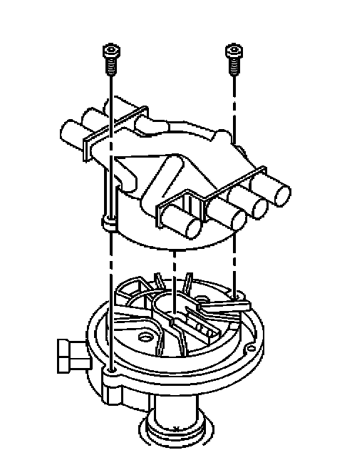
5. Remove the two screws that hold the distributor cap to the housing.
6. Discard the screws.
7. Remove the distributor cap from the housing.
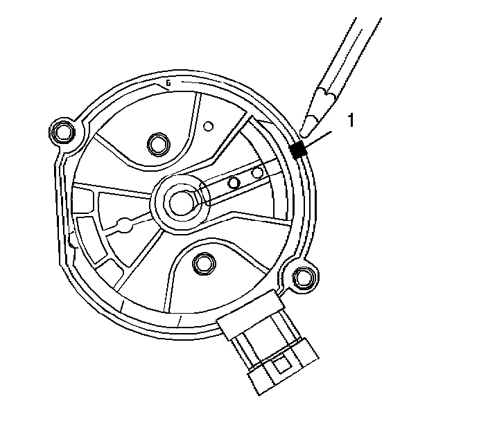
8. Use a grease pencil in order to note the position of the rotor in relation to the distributor housing (1).
9. Mark the distributor housing and the intake manifold with a grease pencil.
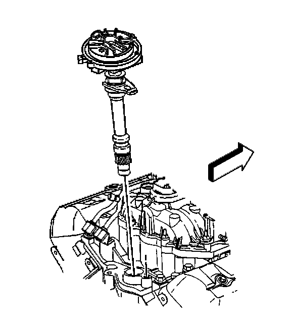
10. Remove the mounting clamp hold down bolt.
11. Remove the distributor.
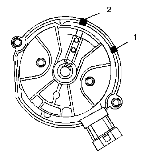
12. As the distributor is being removed from the engine, watch the rotor move in a counter-clockwise direction about 42 degrees. This will appear as slightly more than 1 clock position.
13. Note the position of the rotor segment.
14. Place a second mark on the base of the distributor (2). This will aid in achieving proper rotor alignment during the distributor installation.
INSTALLATION PROCEDURE 1
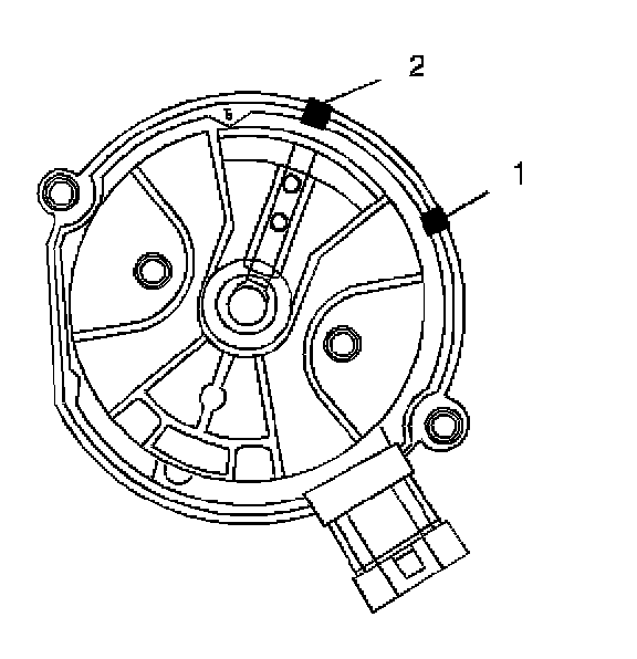
1. If installing a new distributor assembly, place 2 marks on the new distributor housing in the same location as the 2 marks on the original housing.
2. Remove the new distributor cap, if necessary.
3. Align the rotor with the second mark (2).
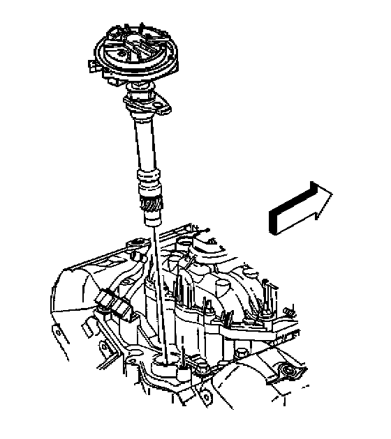
4. Guide the distributor into the engine.
5. Align the hole in the distributor hold-down base over the mounting hole in the intake manifold.
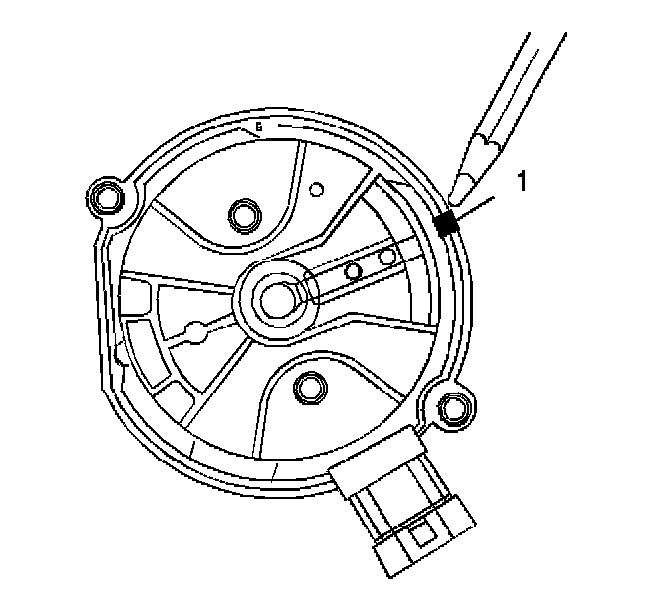
6. As the distributor is being installed, observe the rotor moving in a clockwise direction about 42 degrees.
7. Once the distributor is completely seated, the rotor segment should be aligned with the mark on the distributor base (1).
- If the rotor segment is not aligned with the number 1 mark, the driven gear teeth and the camshaft have meshed one or more teeth out of alignment.
- In order to correct this condition, remove the distributor and reinstall the distributor.
NOTE: Refer to Fastener Notice in Service Precautions.
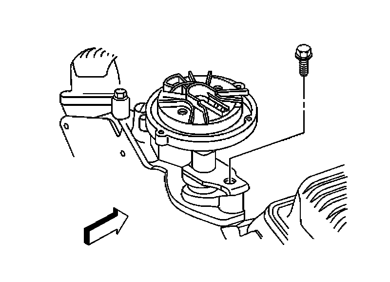
8. Install the distributor mounting clamp bolt.
Tighten
Tighten the distributor clamp bolt to 25 N.m (18 lb ft).
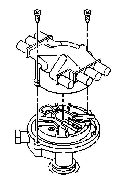
9. Install the distributor cap.
10. Install two new distributor cap screws.
Tighten
Tighten the screws to 2.4 N.m (21 lb in).
11. Install the electrical connector to the distributor.
12. Install the spark plug wires to the distributor cap.
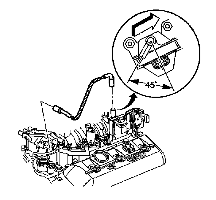
13. Install the ignition coil wire. Note the correct orientation of the wire boot.
IMPORTANT: If the malfunction indicator lamp (MIL) is turned ON after installing the distributor, and a DTC P1345 is found, the distributor has been installed incorrectly.
14. Refer to installation procedure 2 if malfunction indicator lamp is turned ON after installing the distributor.
INSTALLATION PROCEDURE 2
IMPORTANT: Rotate the number 1 cylinder to top dead center (TDC) of the compression stroke. The engine front cover has 2 alignment tabs and the crankshaft balancer has 2 alignment marks (spaced 90 degrees apart) which are used for positioning number 1 piston at top dead center (TDC). With the piston on the compression stroke and at top dead center, the crankshaft balancer alignment mark (1) must align with the engine front cover tab (2) and the crankshaft balancer alignment mark (4) must align with the engine front cover tab (3).

1. Rotate the crankshaft balancer clockwise until the alignment marks on the crankshaft balancer are aligned with the tabs on the engine front cover and the number 1 piston is at top dead center of the compression stroke.
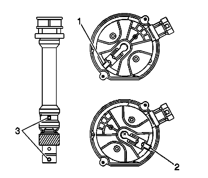
2. Align white paint mark on the bottom stem of the distributor, and the pre-drilled indent hole in the bottom of the gear (3).
NOTE: Refer to Distributor Driven Gear Can Be Installed in Multiple Positions Notice in Service Precautions.
3. With the gear in this position, the rotor segment should be positioned as shown for a V6 engine (1) or V8 engine (2).
- The alignment will not be exact.
- If the driven gear is installed incorrectly, the dimple will be approximately 180 degrees opposite of the rotor segment when the gear is installed in the distributor.
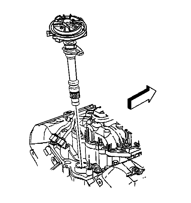
4. Using a long screw driver, align the oil pump drive shaft to the drive tab of the distributor.
5. Guide the distributor into the engine. Ensure that the spark plug towers are perpendicular to the centerline of the engine.
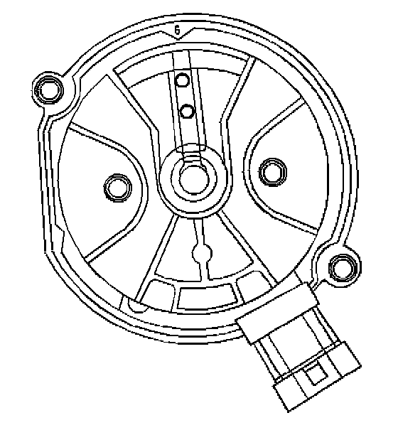
6. Once the distributor is fully seated, the rotor segment should be aligned with the pointer cast into the distributor base.
- There may be a 6 cast into this pointer, indicating that the distributor is to be used on a 6 cylinder engine or an 8, indicating that the distributor is to be used on a 8 cylinder engine.
- If the rotor segment does not come within a few degrees of the pointer, the gear mesh between the distributor and the camshaft may be off a tooth or more.
- If this is the case, repeat the procedure again in order to achieve proper alignment.
NOTE: Refer to Fastener Notice in Service Precautions.

7. Install the distributor mounting clamp bolt.
Tighten
Tighten the distributor clamp bolt to 25 N.m (18 lb ft).
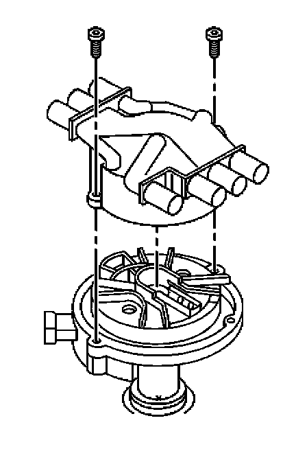
8. Install the distributor cap.
9. Install two new distributor cap screws.
Tighten
Tighten the screws to 2.4 N.m (21 lb in).
10. Install the electrical connector to the distributor.
11. Install the spark plug wires to the distributor cap.
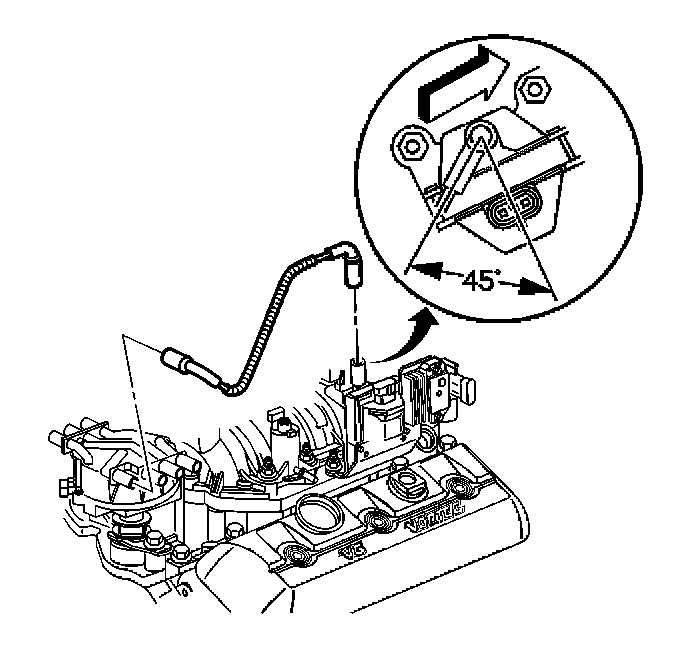
12. Install the ignition coil wire. Note the correct orientation of the wire boot.
IMPORTANT: If the MIL is turned ON after installing the distributor, and a DTC P1345 is found, the distributor has been installed incorrectly.
13. Repeat installation procedure 2 if the malfunction indicator lamp is turned ON after installing the distributor.
REMOVAL PROCEDURE
NOTE: There are two procedures available to install the distributor. Use Installation Procedure 1 when the crankshaft has NOT been rotated from the original position. Use Installation Procedure 2 when any of the following components are removed:
- The intake manifold
- The cylinder head
- The camshaft
- The timing chain or sprockets
- The complete engine
If the malfunction indicator lamp (MIL) turns on and DTC P1345 sets after installing the distributor, this indicates an incorrectly installed distributor.
Engine damage or distributor damage may occur. Use Procedure 2 in order to install the distributor.
1. Turn OFF the ignition.
2. Remove air cleaner assembly.
3. Remove the spark plug wires from the distributor cap.
- Twist each spark plug boot 1/2 turn.
- Pull only on the wire boot in order to remove the wire from the distributor cap.
4. Remove the electrical connector from the base of the distributor.
5. Remove the two screws that hold the distributor cap to the housing.
6. Discard the screws.
7. Remove the distributor cap from the housing.
8. Use a grease pencil in order to note the position of the rotor in relation to the distributor housing (1).
9. Mark the distributor housing and the intake manifold with a grease pencil.
10. Remove the mounting clamp hold down bolt.
11. Remove the distributor.
12. As the distributor is being removed from the engine, watch the rotor move in a counter-clockwise direction about 42 degrees. This will appear as slightly more than 1 clock position.
13. Note the position of the rotor segment.
14. Place a second mark on the base of the distributor (2). This will aid in achieving proper rotor alignment during the distributor installation.
INSTALLATION PROCEDURE 1
1. If installing a new distributor assembly, place 2 marks on the new distributor housing in the same location as the 2 marks on the original housing.
2. Remove the new distributor cap, if necessary.
3. Align the rotor with the second mark (2).
4. Guide the distributor into the engine.
5. Align the hole in the distributor hold-down base over the mounting hole in the intake manifold.
6. As the distributor is being installed, observe the rotor moving in a clockwise direction about 42 degrees.
7. Once the distributor is completely seated, the rotor segment should be aligned with the mark on the distributor base (1).
- If the rotor segment is not aligned with the number 1 mark, the driven gear teeth and the camshaft have meshed one or more teeth out of alignment.
- In order to correct this condition, remove the distributor and reinstall the distributor.
NOTE: Refer to Fastener Notice in Service Precautions.
8. Install the distributor mounting clamp bolt.
Tighten
Tighten the distributor clamp bolt to 25 N.m (18 lb ft).
9. Install the distributor cap.
10. Install two new distributor cap screws.
Tighten
Tighten the screws to 2.4 N.m (21 lb in).
11. Install the electrical connector to the distributor.
12. Install the spark plug wires to the distributor cap.
13. Install the ignition coil wire. Note the correct orientation of the wire boot.
IMPORTANT: If the malfunction indicator lamp (MIL) is turned ON after installing the distributor, and a DTC P1345 is found, the distributor has been installed incorrectly.
14. Refer to installation procedure 2 if malfunction indicator lamp is turned ON after installing the distributor.
INSTALLATION PROCEDURE 2
IMPORTANT: Rotate the number 1 cylinder to top dead center (TDC) of the compression stroke. The engine front cover has 2 alignment tabs and the crankshaft balancer has 2 alignment marks (spaced 90 degrees apart) which are used for positioning number 1 piston at top dead center (TDC). With the piston on the compression stroke and at top dead center, the crankshaft balancer alignment mark (1) must align with the engine front cover tab (2) and the crankshaft balancer alignment mark (4) must align with the engine front cover tab (3).
1. Rotate the crankshaft balancer clockwise until the alignment marks on the crankshaft balancer are aligned with the tabs on the engine front cover and the number 1 piston is at top dead center of the compression stroke.
2. Align white paint mark on the bottom stem of the distributor, and the pre-drilled indent hole in the bottom of the gear (3).
NOTE: Refer to Distributor Driven Gear Can Be Installed in Multiple Positions Notice in Service Precautions.
3. With the gear in this position, the rotor segment should be positioned as shown for a V6 engine (1) or V8 engine (2).
- The alignment will not be exact.
- If the driven gear is installed incorrectly, the dimple will be approximately 180 degrees opposite of the rotor segment when the gear is installed in the distributor.
4. Using a long screw driver, align the oil pump drive shaft to the drive tab of the distributor.
5. Guide the distributor into the engine. Ensure that the spark plug towers are perpendicular to the centerline of the engine.
6. Once the distributor is fully seated, the rotor segment should be aligned with the pointer cast into the distributor base.
- There may be a 6 cast into this pointer, indicating that the distributor is to be used on a 6 cylinder engine or an 8, indicating that the distributor is to be used on a 8 cylinder engine.
- If the rotor segment does not come within a few degrees of the pointer, the gear mesh between the distributor and the camshaft may be off a tooth or more.
- If this is the case, repeat the procedure again in order to achieve proper alignment.
NOTE: Refer to Fastener Notice in Service Precautions.
7. Install the distributor mounting clamp bolt.
Tighten
Tighten the distributor clamp bolt to 25 N.m (18 lb ft).
8. Install the distributor cap.
9. Install two new distributor cap screws.
Tighten
Tighten the screws to 2.4 N.m (21 lb in).
10. Install the electrical connector to the distributor.
11. Install the spark plug wires to the distributor cap.
12. Install the ignition coil wire. Note the correct orientation of the wire boot.
IMPORTANT: If the MIL is turned ON after installing the distributor, and a DTC P1345 is found, the distributor has been installed incorrectly.
13. Repeat installation procedure 2 if the malfunction indicator lamp is turned ON after installing the distributor.
Factory Service Tools
Use the Manual With the Right Hardware
Pair factory procedures with proven DIY tools so the instructions are easier to execute.
Disclosure: Verified tool recommendations may earn an affiliate commission at no cost to you.
When to See a Mechanic
Stop DIY work and contact a certified mechanic immediately if any of the following apply:
- • You smell fuel, burning insulation, or see smoke.
- • Brakes feel soft, pull hard to one side, or make grinding noises.
- • The engine overheats, stalls repeatedly, or misfires under load.
- • You are missing required tools, torque specs, or safe lifting equipment.
- • You are not confident in the next step or safety outcome.
Rather have a pro handle this?
A certified mobile mechanic comes to your home or office. They bring the tools, you stay comfortable. No tow truck, no waiting room, no surprises.
Comes to youSame-day available12-month warranty
Get a Free QuoteNo obligation. See pricing before you book.