
Safety Warning
DIY auto repair can cause serious injury, fire, or vehicle damage. These guides are for informational purposes only. Always follow OEM torque specs, wear PPE, and consult a certified mechanic if you are unsure. You are solely responsible for your safety.
2011 Ford Escape 4WD L4-2.5LFACTORY OEM SERVICE PROCEDURE
Mainshaft
Mainshaft
Disassembly
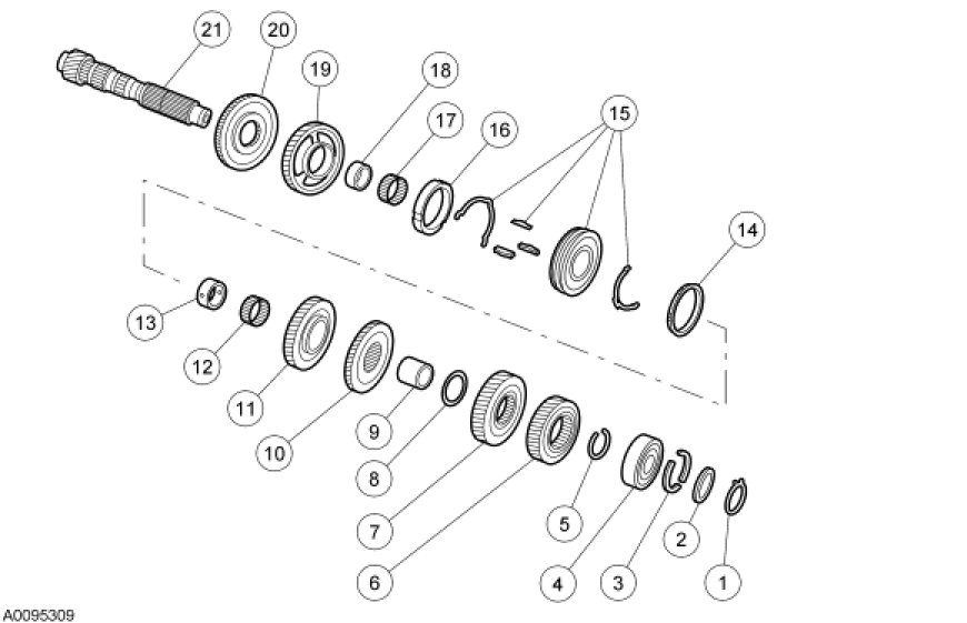
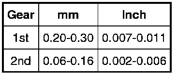
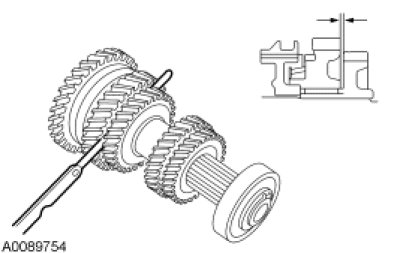
1. Prior to disassembly of the mainshaft, measure and record the end play for 1st and 2nd gears. Refer to the following chart for standard values:
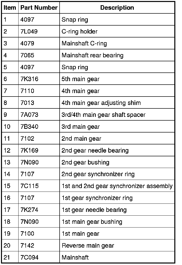
2. Remove and discard the snap ring.
3. Remove the C-ring holder.
4. Remove the mainshaft C-ring.
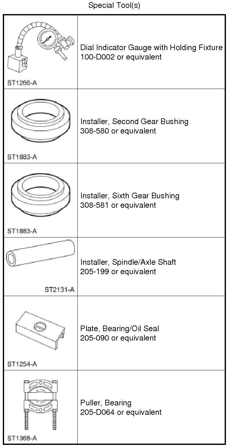
5. Using the Bearing Puller and a suitable press, remove the mainshaft rear bearing.
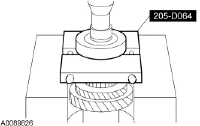
6. Remove and discard the snap ring.
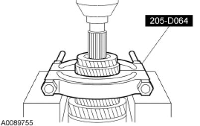
7. Using the Bearing Puller and a suitable press, remove the 5th main gear and the 4th main gear together.
- Discard both gears.
8. Remove the 4th gear main adjusting shim.
9. Remove the 3rd/4th gear shaft spacer.
10. Remove the 3rd main gear, 2nd main gear, 2nd gear needle bearing, 2nd gear bushing, 1st and 2nd gear synchronizer assembly, 1st and 2nd gear synchronizer rings, 1st main gear, reverse main gear, 1st gear needle bearing and 1st gear bushing together.
- Discard the 3rd main gear, the reverse main gear, and the 1st and 2nd gear synchronizer assembly.
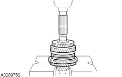
11. Inspect all mainshaft parts for damage, peeling, dents, uneven wear or bending. Install new parts as necessary.
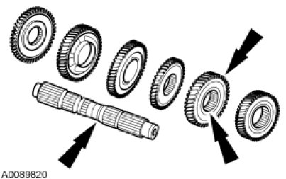
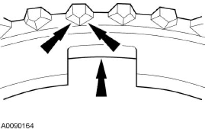
12. Inspect the synchronizer rings for damage. Install new parts as necessary.
13. NOTE: The outer synchronizer ring, synchronizer cone and inner synchronizer ring have a set control clearance. If the measurement exceeds specification, install all 3 parts as a set.
Check the clearances of the double cone synchronizer for 1st gear. If any of the clearances are beyond specification, install new parts as a set.
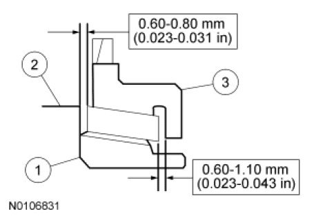
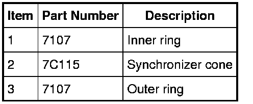
14. NOTE: If the difference in measurements is greater than 0.2 mm (0.007 in), install new parts.
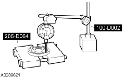
Using the Dial Indicator Gauge with Holding Fixture and the Bearing Puller, measure the clearance at 2 or more points diagonally between the synchronizer cone and the inner synchronizer ring. Install new parts if not within specification.
15. NOTE: If the difference in measurements is greater than 0.2 mm (0.007 in), install new parts.
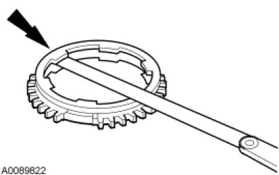
Measure the clearance between the outer synchronizer ring and the synchronizer cone at 2 or more points diagonally opposite and calculate the mean value. Install new parts if not within specification.
16. NOTE: The outer synchronizer ring, synchronizer cone and inner synchronizer ring have a set control clearance. If the measurement exceeds specification, install all 3 parts new as a set.
Check the clearances of the triple cone synchronizer for 2nd gear. If any of the clearances are beyond specification, install new parts as a set.
17. NOTE: If the difference in measurements is greater than 0.3 mm (0.011 in), install new parts.
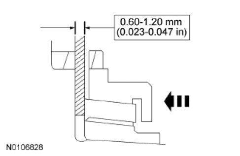
Measure the clearance at 2 or more points diagonally opposite and calculate the mean. If the measurement is not within specification, install new parts.
18. NOTE: If the difference in measurements is greater than 0.17 mm (0.006 in) install new parts.
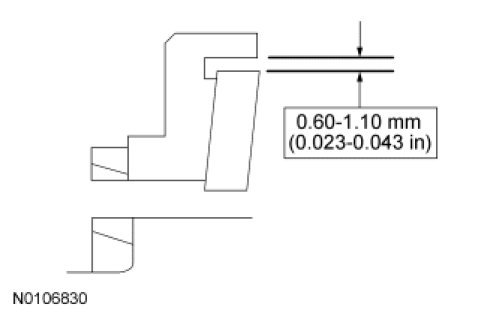
Measure the clearance at 2 or more points diagonally opposite and calculate the mean. If the measurement is not within specification, install new parts.
19. NOTE: If the difference in measurements is greater than 0.3 mm (0.011 in), install new parts.
Measure the clearance at 2 or more points diagonally opposite and calculate the mean. If the measurement is not within specification, install new parts.
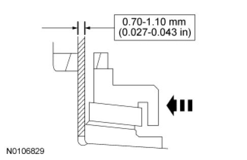
Assembly
1. NOTICE: Be careful with the orientation of the reverse main gear or damage to the component may occur.
Position the reverse main gear on the mainshaft.
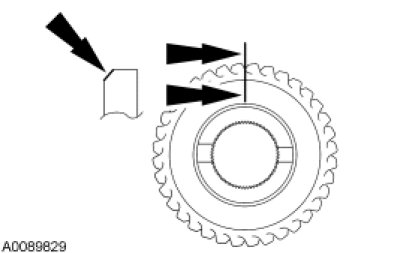
2. Using the Spindle/Axle Shaft Installer, press on a new reverse main gear.
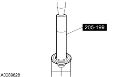
3. Install the 1st main gear.
4. Using the Bearing/Oil Seal Plate and the Sixth Gear Bushing Installer, press on the 1st main gear bushing.
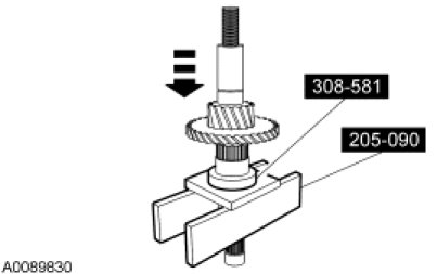
5. Install the 1st gear needle bearing.
6. Install the 1st gear synchronizer ring.
7. NOTE: Make sure the synchronizer side with 3 notches is facing 1st gear and the synchronizer side with 4 notches is facing 2nd gear.
Position a new 1st and 2nd gear synchronizer assembly on the mainshaft.
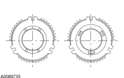
8. Using the Spindle/Axle Shaft Installer and the Bearing Puller, press on the 1st and 2nd gear synchronizer assembly.
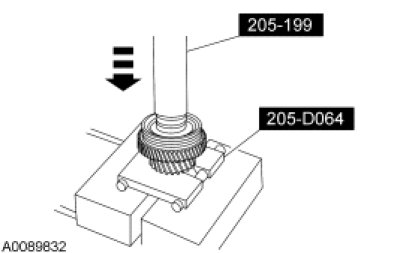
9. Install the 2nd gear synchronizer ring.
10. Using the Bearing/Oil Seal Plate and the Second Gear Bushing Installer, press on the 2nd gear bushing.
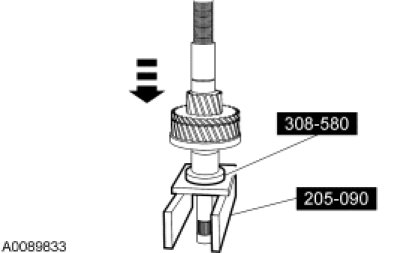
11. Install the 2nd gear needle bearing.
12. Install the 2nd main gear.
13. NOTE: Be careful with the orientation of the 3rd main gear.
Using the Spindle/Axle Shaft Installer and the Bearing Puller, press on a new 3rd main gear.
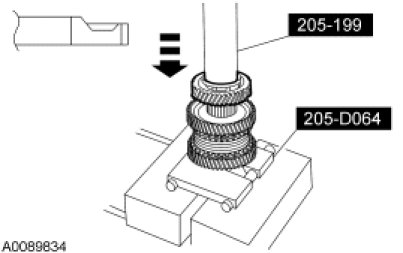
14. Install the 3rd/4th main gear shaft spacer.
15. NOTE: Only one adjusting shim can be installed.
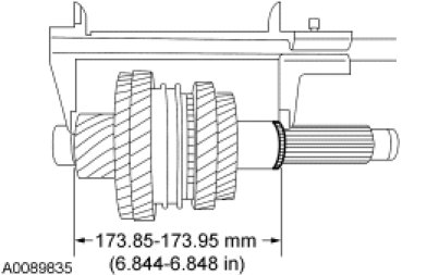
Measure the mainshaft components as indicated to select the appropriate 4th main gear adjusting shim. Refer to the following table for shim thicknesses and install the 4th main gear adjusting shim:
16. NOTE: Be careful with the orientation of the 4th main gear.
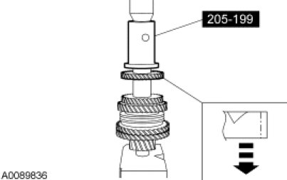
Using the Spindle/Axle Shaft Installer, press on a new 4th main gear.
17. NOTE: Be careful with the orientation of the 5th main gear.
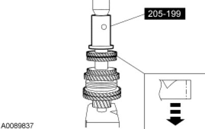
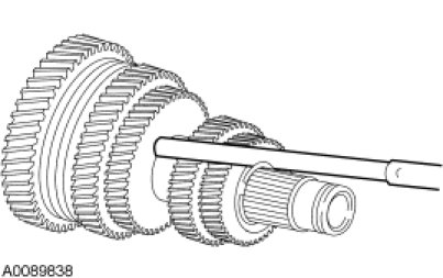
Using the Spindle/Axle Shaft Installer, press on a new 5th main gear.
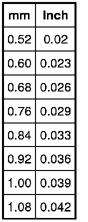
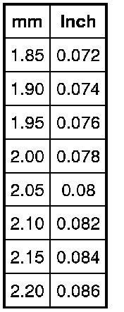
18. Measure the gap between the snap ring and the 5th main gear. The end play should be less than 0.1 mm (0.0039 in). Refer to the following chart to select the appropriate snap ring thickness and install a new snap ring:
19. NOTE: Be careful with the orientation of the mainshaft rear bearing.
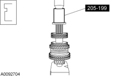
Using the Spindle/Axle Shaft Installer, press on the mainshaft rear bearing.
20. Measure the gap between the mainshaft C-ring and the mainshaft rear bearing. Refer to the following chart to select the appropriate C-ring thickness and install the C-ring:

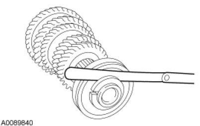
21. Install the C-ring holder.
22. Install a new snap ring.
Factory Service Tools
Use the Manual With the Right Hardware
Pair factory procedures with proven DIY tools so the instructions are easier to execute.
Disclosure: Verified tool recommendations may earn an affiliate commission at no cost to you.
When to See a Mechanic
Stop DIY work and contact a certified mechanic immediately if any of the following apply:
- • You smell fuel, burning insulation, or see smoke.
- • Brakes feel soft, pull hard to one side, or make grinding noises.
- • The engine overheats, stalls repeatedly, or misfires under load.
- • You are missing required tools, torque specs, or safe lifting equipment.
- • You are not confident in the next step or safety outcome.
Rather have a pro handle this?
A certified mobile mechanic comes to your home or office. They bring the tools, you stay comfortable. No tow truck, no waiting room, no surprises.
Comes to youSame-day available12-month warranty
Get a Free QuoteNo obligation. See pricing before you book.