
Safety Warning
DIY auto repair can cause serious injury, fire, or vehicle damage. These guides are for informational purposes only. Always follow OEM torque specs, wear PPE, and consult a certified mechanic if you are unsure. You are solely responsible for your safety.
2011 Ford Escape 4WD L4-2.5LFACTORY OEM SERVICE PROCEDURE
Transmission Position Sensor/Switch: Service and Repair
Digital Transmission Range (TR) Sensor
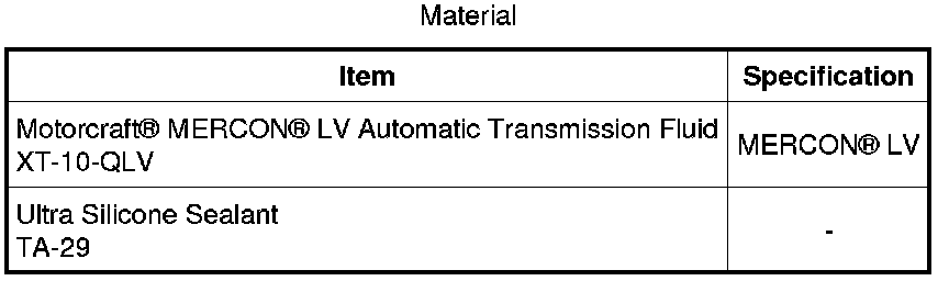
Removal
All vehicles
1. With the vehicle in NEUTRAL, position it on a hoist. For additional information, refer to Jacking and Lifting Service and Repair.
3.0L engine
2. Remove the Air Cleaner (ACL) outlet pipe. For additional information, refer to Intake Air Distribution and Filtering - 3.0L (4V) Air Cleaner Outlet Pipe.
2.5L engine
3. Remove the ACL outlet pipe. For additional information, refer to Intake Air Distribution and Filtering - 2.5L Air Cleaner Outlet Pipe.
All vehicles
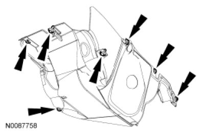
4. Remove the retainers and the LH splash shield.
3.0L engine
5. Remove the retainers and the RH splash shield.

All vehicles
6. Remove the transmission fluid drain plug and allow the transmission fluid to drain.
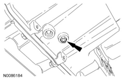
7. Install the transmission fluid drain plug.
- Tighten to 12 Nm (106 lb-in).
3.0L engine
8. Drain the cooling system. For additional information, refer to Cooling System Draining, Filling and Bleeding in Engine Cooling Cooling System Draining, Filling and Bleeding.
9. Disconnect the upper radiator hose from the coolant pump housing and position it aside.
10. Disconnect the lower radiator hose from the thermostat housing and position it aside.
All vehicles
11. Disconnect the selector lever cable end from the manual control lever.
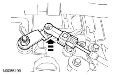
12. Remove the nut and the manual control lever.
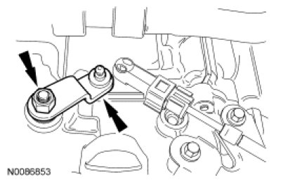
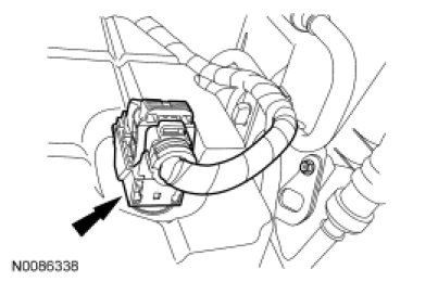
13. Disconnect the transaxle vehicle harness electrical connector.
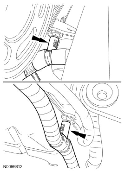
14. Remove the transaxle electrical wiring harness retainers from the transmission fluid pan stud bolts.
15. Remove the transmission fluid cooler tube bracket nuts from the main control cover studs and position the transmission fluid cooler tubes and bracket aside.
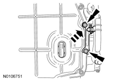
16. NOTE: Note the location of the stud bolts for assembly.
Remove the 8 bolts, 5 stud bolts and the main control cover.
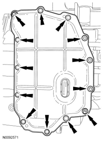
17. Remove the main control cover grommet.
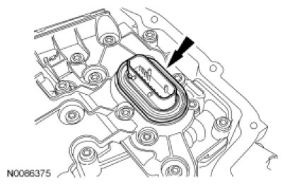
18. Disconnect the Transmission Range (TR) sensor electrical connector.
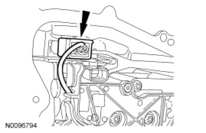
19. Remove the bolt and the TR sensor detent spring.
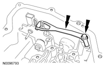
20. Using a small pair of Vise Grips(R) or an equivalent suitable tool, remove and discard the TR sensor locking pin.
21. Remove the TR sensor in the following sequence.
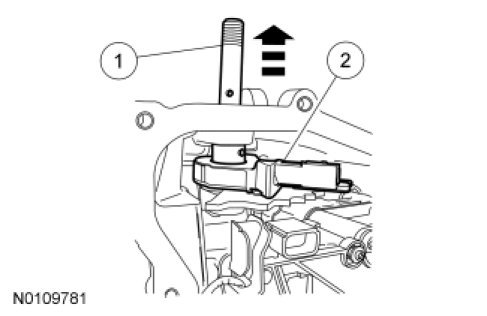
1. Hold the TR sensor in place and slide the manual shaft outward until the manual shaft is out of the transaxle case.
2. Remove the TR sensor from the transaxle, leaving the park pawl actuating rod attached to the TR sensor.
Installation
All vehicles
1. NOTE: The TR sensor is easier to install into the transaxle from under the vehicle.
Install the TR sensor.
1. Install the TR sensor and park pawl actuating rod in the transaxle case.
2. Install the manual shaft in the transaxle case through the TR sensor.
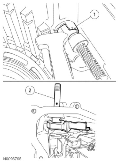
2. Using a suitable tool such as center punch or a 5.5 mm (0.216 in) socket and a 101.6 mm (4 in) extension 1/4-inch drive, install a new TR sensor locking pin.
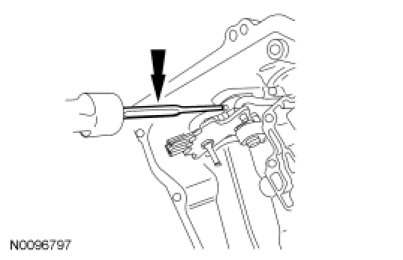
3. Install the TR sensor detent spring and bolt.
- Tighten to 13 Nm (115 lb-in).
4. Connect the TR sensor electrical connector.
5. Install the main control cover grommet.
6. Clean the main control cover sealing surface.
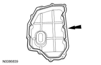
7. Apply silicone to the main control sealing surface of the transaxle case.
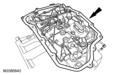
8. Position the main control cover in place.
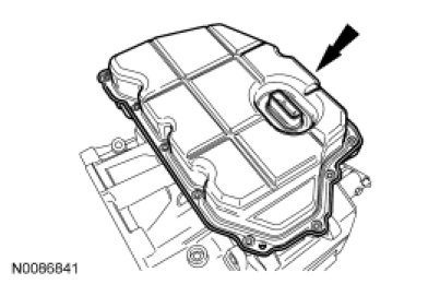
9. NOTICE: Inspect the main control cover grommet to make sure that the seal is on the inside of the main control cover. Transmission fluid leak will occur.
NOTE: Install the stud bolts in the locations noted during disassembly.
Install the main control cover 8 bolts and 5 stud bolts.
- Tighten to 12 Nm (106 lb-in).
10. Position the transmission fluid cooler tube bracket and transmission fluid cooler tubes in place and install the 2 nuts.
- Tighten to 9 Nm (80 lb-in).
11. Connect the transaxle vehicle harness electrical connector.
12. Connect the transaxle electrical wiring harness retainers to the transmission fluid pan stud bolts.
13. NOTICE: Make sure that when installing the manual control lever it is fully seated onto the manual control lever shaft or damage to the manual control lever shaft will occur and the lever will come loose.
NOTICE: Make sure to hold the manual control lever while tightening the manual control lever nut or damage to the manual control lever and park components will occur.
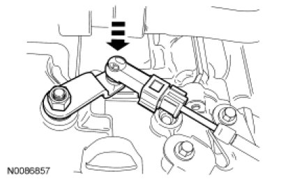
Install the manual control lever and the nut.
- Tighten to 24 Nm (18 lb-ft).
14. Connect the selector lever cable end to the manual control lever with the manual control lever and selector lever in DRIVE. Check selector lever cable adjustment. For additional information, refer to Automatic Transaxle/Transmission External Controls - 6F35 Adjustments.
3.0L engine
15. Connect the lower radiator hose onto the thermostat housing.
16. Connect the upper radiator hose onto the coolant pump housing.
All vehicles
17. Install the LH splash shield and the retainers.
3.0L engine
18. Install the RH splash shield and the retainers.
2.5L engine
19. Install the ACL outlet pipe. For additional information, refer to Intake Air Distribution and Filtering - 2.5L Air Cleaner Outlet Pipe.
3.0L engine
20. Install the ACL outlet pipe. For additional information, refer to Intake Air Distribution and Filtering - 3.0L (4V) Air Cleaner Outlet Pipe.
21. Fill and bleed the cooling system. For additional information, refer to Cooling System Draining, Filling and Bleeding in Engine Cooling Cooling System Draining, Filling and Bleeding.
All vehicles
22. Fill the transaxle with clean transmission fluid.
23. Using the scan tool with the engine running, check and make sure that the transmission is at normal operating temperature 85-93°C (185-200°F). Check and adjust the transmission fluid level and check for any leaks. If transmission fluid is needed, add transmission fluid in increments of 0.24L (0.5 pt) until the correct level is achieved.
Factory Service Tools
Use the Manual With the Right Hardware
Pair factory procedures with proven DIY tools so the instructions are easier to execute.
Disclosure: Verified tool recommendations may earn an affiliate commission at no cost to you.
When to See a Mechanic
Stop DIY work and contact a certified mechanic immediately if any of the following apply:
- • You smell fuel, burning insulation, or see smoke.
- • Brakes feel soft, pull hard to one side, or make grinding noises.
- • The engine overheats, stalls repeatedly, or misfires under load.
- • You are missing required tools, torque specs, or safe lifting equipment.
- • You are not confident in the next step or safety outcome.
Rather have a pro handle this?
A certified mobile mechanic comes to your home or office. They bring the tools, you stay comfortable. No tow truck, no waiting room, no surprises.
Comes to youSame-day available12-month warranty
Get a Free QuoteNo obligation. See pricing before you book.