
Safety Warning
DIY auto repair can cause serious injury, fire, or vehicle damage. These guides are for informational purposes only. Always follow OEM torque specs, wear PPE, and consult a certified mechanic if you are unsure. You are solely responsible for your safety.
2011 Ford Escape 4WD L4-2.5LFACTORY OEM SERVICE PROCEDURE
Valve Cover
Valve Cover
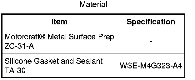
Valve Cover (View 1 of 2)
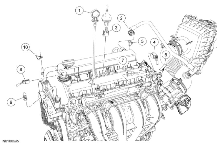
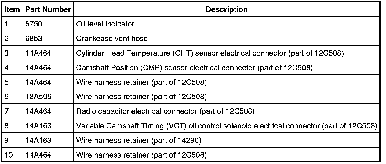
Valve Cover (2 of 2)
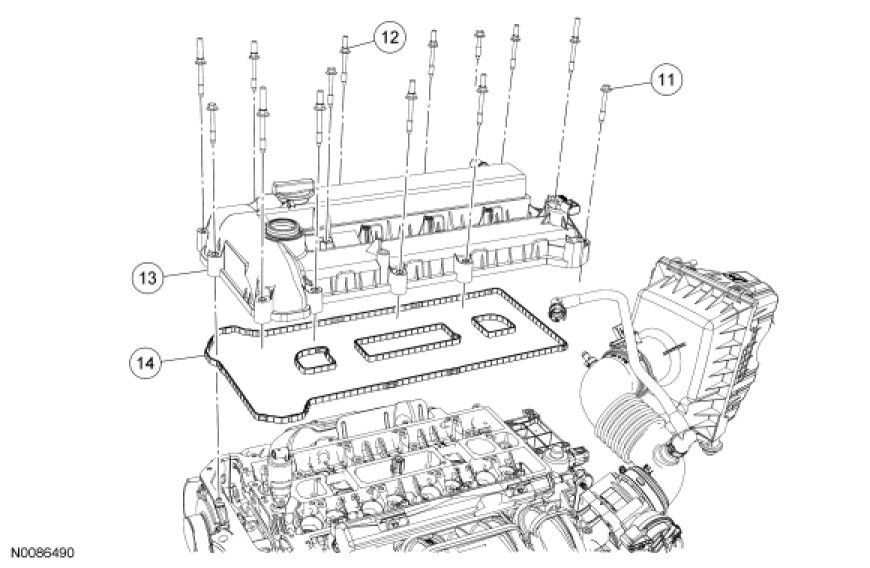
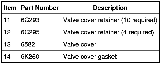
Removal
NOTICE: During engine repair procedures, cleanliness is extremely important. Any foreign material, including any material created while cleaning gasket surfaces, that enters the oil passages, coolant passages or the oil pan can cause engine failure.
1. Remove the oil level indicator.
2. Remove the ignition coil-on-plugs. For additional information, refer to Engine Ignition - 2.5L Ignition Coil-On-Plug.
3. Disconnect the crankcase vent hose.
4. Disconnect the Cylinder Head Temperature (CHT) sensor electrical connector.
5. Disconnect the Camshaft Position (CMP) sensor electrical connector.
6. Disconnect the radio capacitor electrical connector.
7. Disconnect the Variable Camshaft Timing (VCT) solenoid electrical connector.
8. Detach all of the wiring harness retainers from the valve cover studs and position the harness aside.
9. Remove the 14 valve cover retainers, the valve cover and gasket.
Installation
1. NOTICE: Do not use metal scrapers, wire brushes, power abrasive discs or other abrasive means to clean the sealing surfaces. These tools cause scratches and gouges which make leak paths.
Clean and inspect the sealing surfaces.
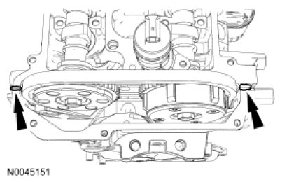
2. NOTE: The valve cover must be secured within 4 minutes of silicone gasket application. If the valve cover is not secured within 4 minutes, the sealant must be removed and the sealing area cleaned with metal surface prep.
Apply silicone gasket and sealant to the locations shown.
3. NOTE: Clean and inspect the gasket. Install a new gasket, if necessary.
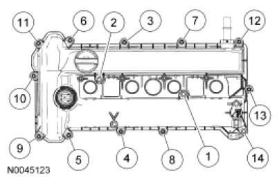
Install the valve cover, gasket and retainers.
- Tighten in the sequence shown to 10 Nm (89 lb-in).
4. Position the wiring harness and attach all of the wiring harness retainers to the valve cover studs.
5. Connect the VCT solenoid electrical connector.
6. Connect the radio capacitor electrical connector.
7. Connect the CMP sensor electrical connector.
8. Connect the CHT sensor electrical connector.
9. Connect the crankcase vent hose.
10. Install the ignition coil-on-plugs. For additional information, refer to Engine Ignition - 2.5L Ignition Coil-On-Plug.
11. Install the oil level indicator.
Factory Service Tools
Use the Manual With the Right Hardware
Pair factory procedures with proven DIY tools so the instructions are easier to execute.
Disclosure: Verified tool recommendations may earn an affiliate commission at no cost to you.
When to See a Mechanic
Stop DIY work and contact a certified mechanic immediately if any of the following apply:
- • You smell fuel, burning insulation, or see smoke.
- • Brakes feel soft, pull hard to one side, or make grinding noises.
- • The engine overheats, stalls repeatedly, or misfires under load.
- • You are missing required tools, torque specs, or safe lifting equipment.
- • You are not confident in the next step or safety outcome.
Rather have a pro handle this?
A certified mobile mechanic comes to your home or office. They bring the tools, you stay comfortable. No tow truck, no waiting room, no surprises.
Comes to youSame-day available12-month warranty
Get a Free QuoteNo obligation. See pricing before you book.