
Safety Warning
DIY auto repair can cause serious injury, fire, or vehicle damage. These guides are for informational purposes only. Always follow OEM torque specs, wear PPE, and consult a certified mechanic if you are unsure. You are solely responsible for your safety.
2011 Ford Escape 4WD L4-2.5LFACTORY OEM SERVICE PROCEDURE
Steps 1-50
Engine
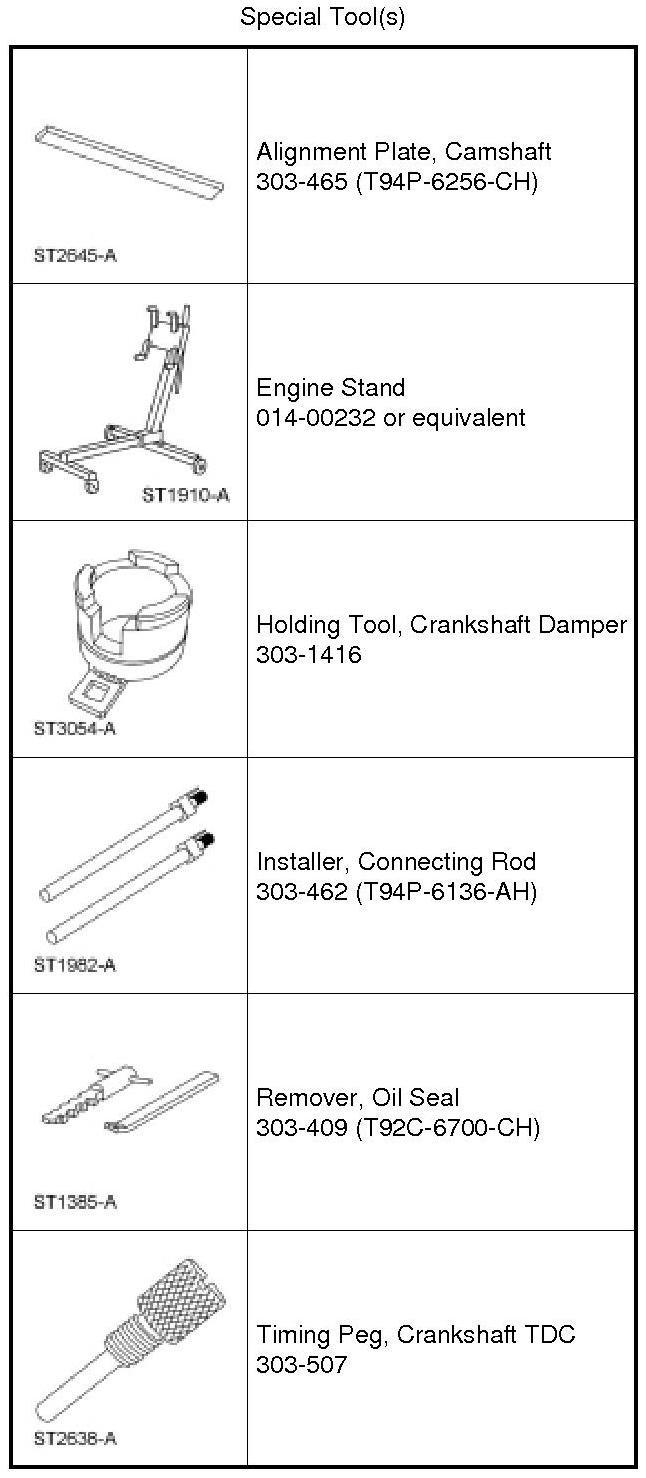
NOTICE: Do not loosen or remove the crankshaft pulley bolt without first installing the special tools as instructed in this procedure. The crankshaft pulley and the crankshaft timing sprocket are not keyed to the crankshaft. The crankshaft, the crankshaft sprocket and the pulley are fitted together by friction, using diamond washers between the flange faces on each part. For that reason, the crankshaft sprocket is also unfastened if the pulley bolt is loosened. Before any repair requiring loosening or removal of the crankshaft pulley bolt, the crankshaft and camshafts must be locked in place by the special service tools, otherwise severe engine damage can occur.
NOTICE: During engine repair procedures, cleanliness is extremely important. Any foreign material (including any material created while cleaning gasket surfaces) that enters the oil passages, coolant passages or the oil pan, can cause engine failure.
NOTE: Due to the precision fit and timing of the balancer shaft assembly, it cannot be removed from the engine block.
NOTE: For additional information, refer to the exploded views under the Engine Assembly procedure.
Vehicles with manual transaxle
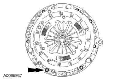
1. WARNING: The clutch disc and clutch pressure plate are heavy and may fall if not held when the bolts are removed. Failure to follow this instruction may result in serious personal injury.
NOTICE: Loosen the bolts evenly to prevent pressure plate damage.
Remove the bolts, clutch pressure plate and clutch disc.
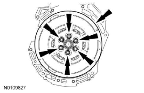
2. Remove the bolts and the flywheel.
Vehicles with automatic transaxle
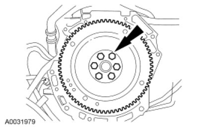
3. Remove the bolts and the flexplate.
All vehicles
4. Mount the engine on a suitable stand.
5. Disconnect the Crankshaft Position (CKP) sensor electrical connector.
- Detach the wiring harness-to-engine retainer.
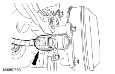
6. Disconnect the generator electrical connection and the 2 wiring harness retainers.
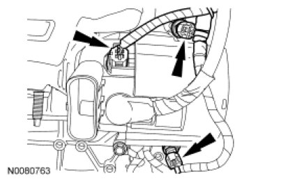
7. Remove the nut and the generator wiring harness.
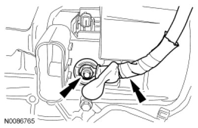
8. Remove the 2 nuts, 1 bolt and the generator.
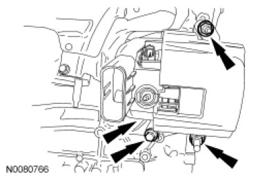
9. Disconnect the Heated Oxygen Sensor (HO2S) electrical connector.
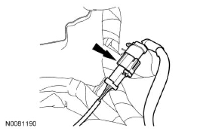
10. Remove the 4 exhaust manifold heat shield bolts and the heat shield.
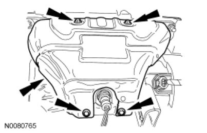
11. Remove and discard the 7 exhaust manifold nuts.
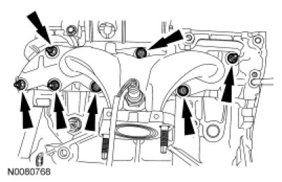
12. Remove the exhaust manifold and discard the exhaust manifold gasket.
13. Remove and discard the 7 exhaust manifold studs.
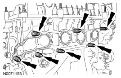
14. Clean and inspect the exhaust manifold. For additional information, refer to Engine System - General Information Exhaust Manifold Cleaning and Inspection.
15. Remove the 2 bolts and the accessory drive belt tensioner.
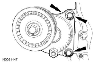
16. Loosen the bolt and remove the accessory drive belt idler pulley.
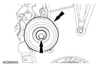
17. Remove the 2 bolts and the accessory drive belt idler pulley and bracket.
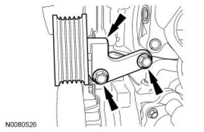
18. Remove the 3 bolts and the coolant pump pulley.
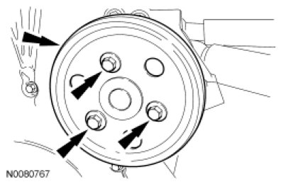
19. Remove the bolts and the coolant pump.
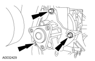
20. Remove the 3 bolts and the thermostat housing assembly.
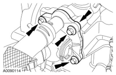
21. Remove the coolant tube retainer from the intake manifold.
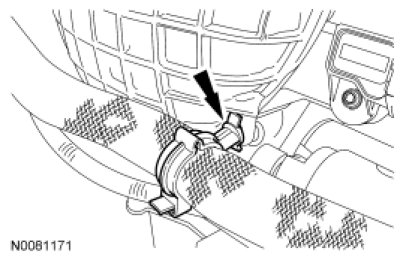
22. Disconnect the Engine Oil Pressure (EOP) switch electrical connector.
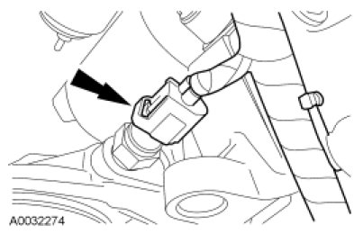
23. Remove the 4 bolts and the oil filter adapter.
- Discard the gasket.
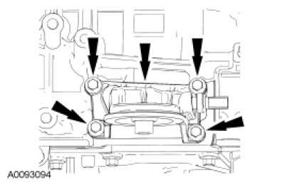
24. If equipped, remove the bolt and capacitor.
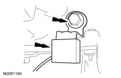
25. Disconnect the Variable Camshaft Timing (VCT) electrical connector.
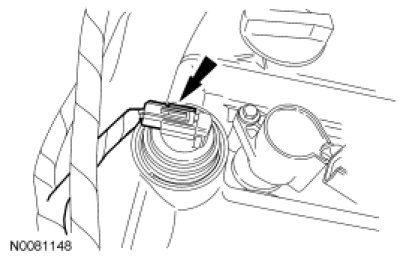
26. Detach the wiring harness retainers from the RH side valve cover stud bolts.
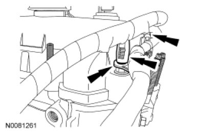
27. Disconnect the crankcase vent hose from the valve cover.
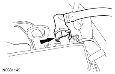
28. Detach the wiring harness retainers from the LH side valve cover stud bolts.
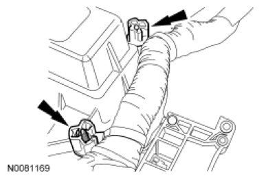
29. Disconnect the Manifold Absolute Pressure (MAP) sensor electrical connector.
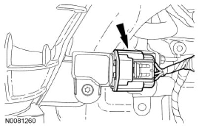
30. Disconnect the electronic throttle control and Evaporative Emission (EVAP) canister purge valve electrical connectors.
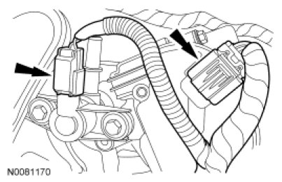
31. Disconnect the EGR valve electrical connector.
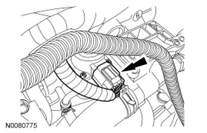
32. Disconnect the Knock Sensor (KS) and detach the 2 wiring harness retainers.
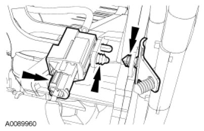
33. Detach all the wiring harness retainers from the intake manifold.
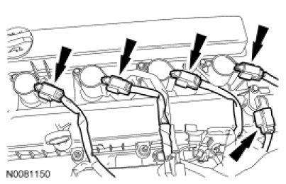
34. Disconnect the 4 coil-on-plugs and Camshaft Position (CMP) sensor electrical connectors.
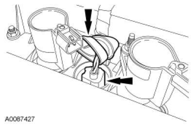
35. Position the rubber boot aside and disconnect the Cylinder Head Temperature (CHT) sensor electrical connector.
36. Disconnect the radio capacitor electrical connector.
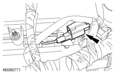
37. Disconnect the 4 fuel injector electrical connectors.
- Detach the 2 wiring harness retainers and remove the wiring harness assembly.
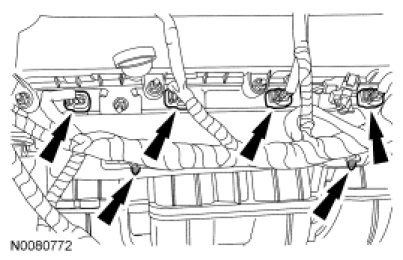
38. Remove the fuel rail insulator.
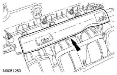
39. Remove the nut and the radio capacitor.
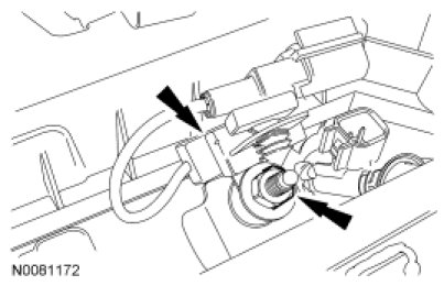
40. Remove the 2 stud bolts, fuel rail and fuel injectors as an assembly.
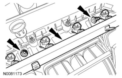
41. Remove the 8 bolts (3 shown) and position the intake manifold aside.
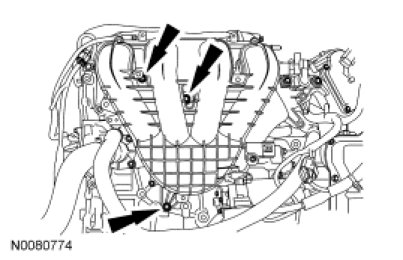
42. NOTICE: If the engine is repaired or replaced because of upper engine failure, typically including valve or piston damage, check the intake manifold for metal debris. If metal debris is found, install a new intake manifold. Failure to follow these instructions can result in engine damage.
Squeeze the 2 crankcase vent oil separator tube tabs and disconnect the tube from the intake manifold.
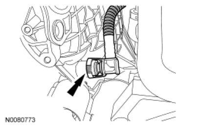
43. Remove the EGR tube.
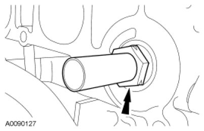
44. Disconnect the coolant hose.
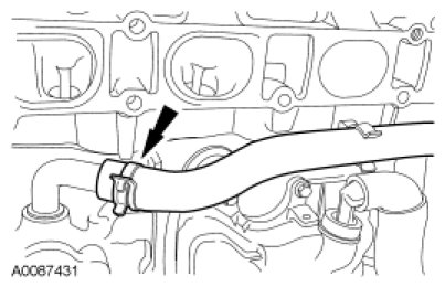
45. Disconnect and remove the coolant hose.
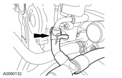
46. Disconnect and remove 2 the coolant hoses.
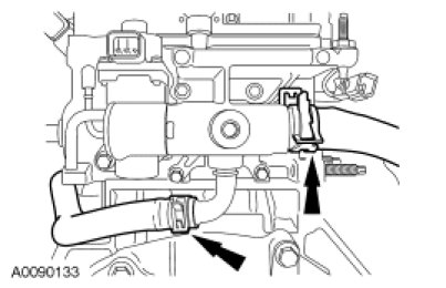
47. Remove the bolt and the KS.

48. Remove the 8 bolts and the crankcase vent oil separator.
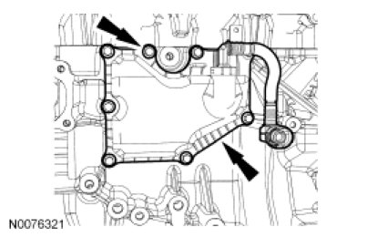
49. If equipped, remove the block heater.
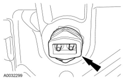
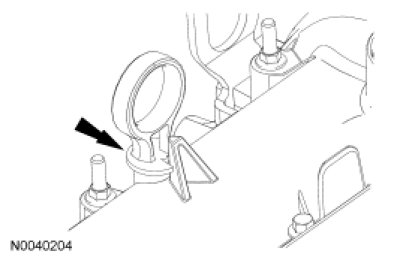
50. Remove the oil level indicator.
Factory Service Tools
Use the Manual With the Right Hardware
Pair factory procedures with proven DIY tools so the instructions are easier to execute.
Disclosure: Verified tool recommendations may earn an affiliate commission at no cost to you.
When to See a Mechanic
Stop DIY work and contact a certified mechanic immediately if any of the following apply:
- • You smell fuel, burning insulation, or see smoke.
- • Brakes feel soft, pull hard to one side, or make grinding noises.
- • The engine overheats, stalls repeatedly, or misfires under load.
- • You are missing required tools, torque specs, or safe lifting equipment.
- • You are not confident in the next step or safety outcome.
Rather have a pro handle this?
A certified mobile mechanic comes to your home or office. They bring the tools, you stay comfortable. No tow truck, no waiting room, no surprises.
Comes to youSame-day available12-month warranty
Get a Free QuoteNo obligation. See pricing before you book.