
Safety Warning
DIY auto repair can cause serious injury, fire, or vehicle damage. These guides are for informational purposes only. Always follow OEM torque specs, wear PPE, and consult a certified mechanic if you are unsure. You are solely responsible for your safety.
2002 Ford Excursion 2WD V10-6.8LFACTORY OEM SERVICE PROCEDURE
Compressor Clutch: Service and Repair
Special Tool(s), Part 1:
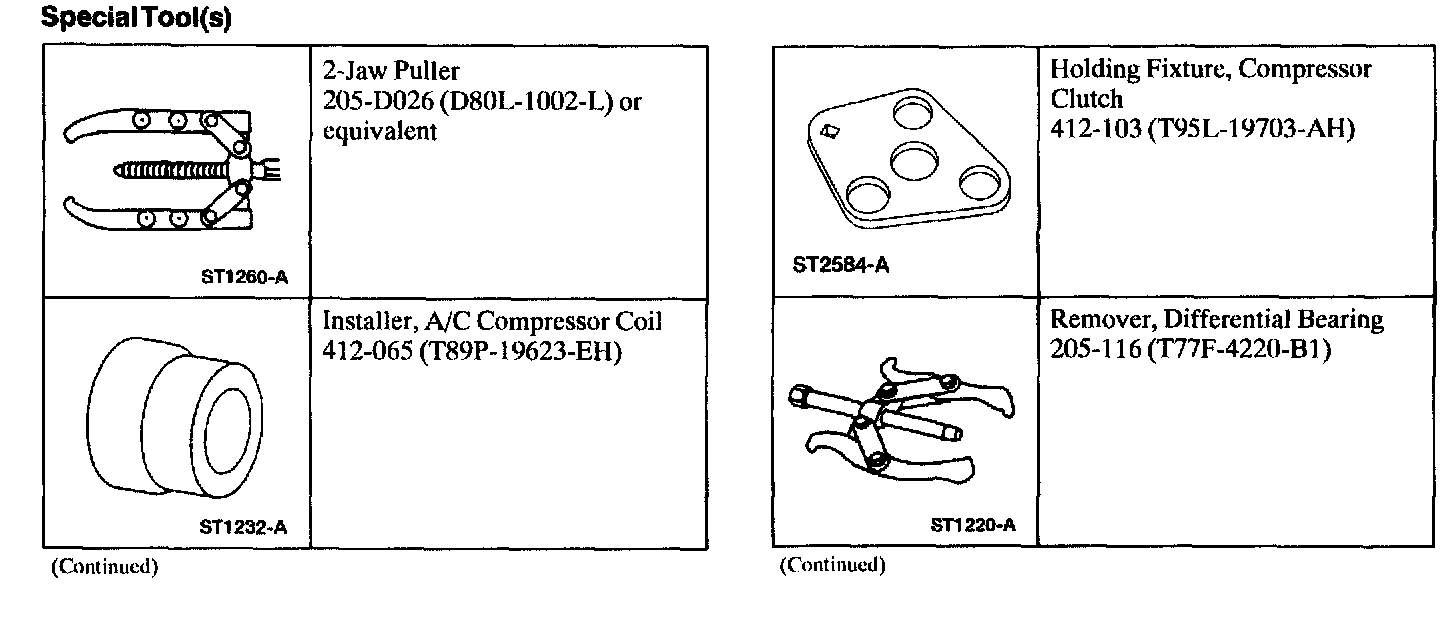
Special Tool(s), Part 2:
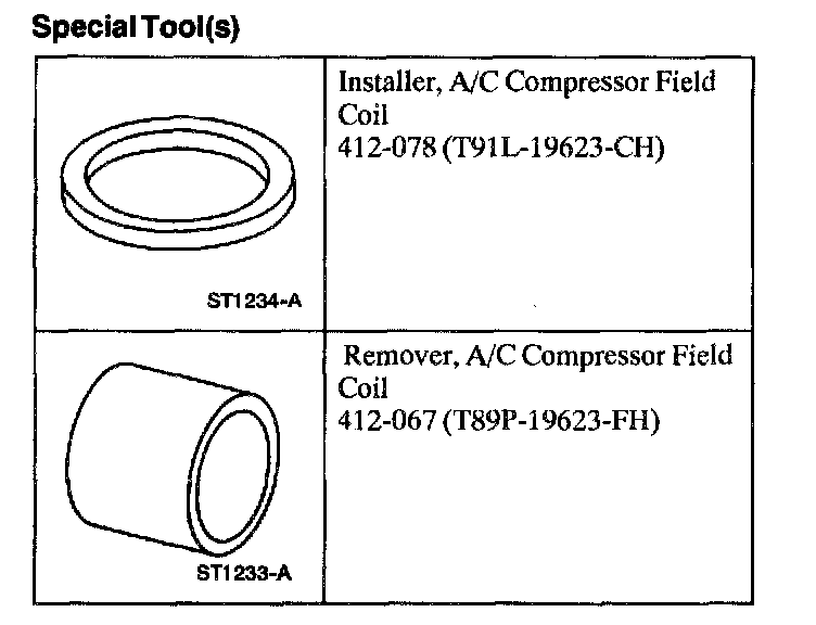
SPECIAL TOOL(S)
REMOVAL
1. Remove the A/C compressor.
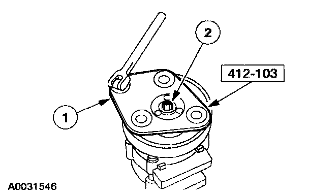
2. Remove the A/C clutch hub retaining bolt.
1 Hold the A/C clutch hub with the special tool.
2 Remove the bolt.
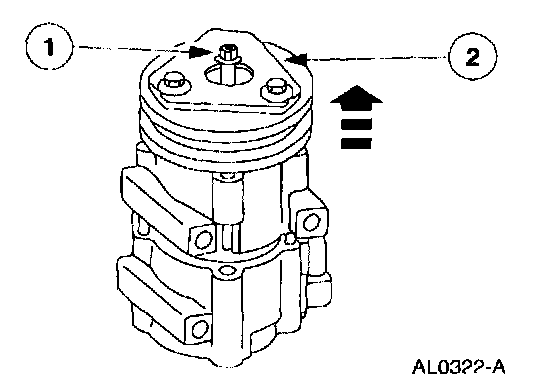
3. Remove the A/C clutch and the A/C clutch hub spacer.
1 Thread an 8 x 1.25 mm bolt into the A/C clutch hub spacer to force it from the compressor shaft.
2 Lift the A/C clutch and the A/C clutch hub spacer from the compressor shaft.
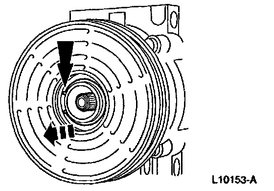
4. Remove the pulley snap ring.
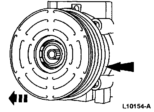
5. Remove the A/C clutch pulley.
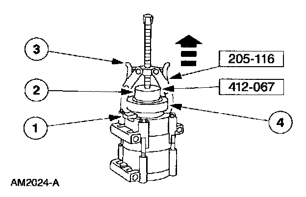
6. Remove the A/C clutch field coil.
1 Note the location of the A/C clutch field coil electrical connector.
2 Install the special tool on the nose opening of the A/C compressor.
3 Install the special tool.
4 Remove the A/C clutch field coil.
CAUTION: Do not use air tools. The A/C clutch field coil can be easily damaged.
INSTALLATION
1. Clean the A/C clutch field coil and the pulley bearing mounting surfaces.
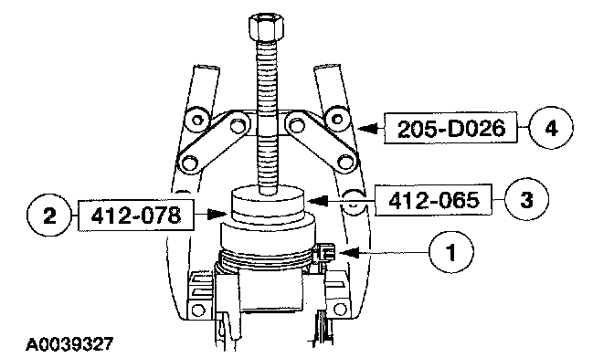
2. Install the A/C clutch field coil.
1 Place the A/C clutch field coil on the A/C compressor with the A/C clutch field coil electrical connector correctly positioned.
2 Place the special tool on the A/C clutch field coil.
3 Place the special tool on the special tool.
4 Use the special tool to install the A/C clutch field coil until bottomed completely against the A/C compressor.
CAUTION: Do not use air tools. The A/C clutch field coil can be easily damaged.
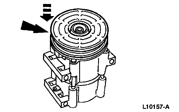
3. Install the A/C clutch pulley.
NOTE: The A/C clutch pulley is a tight fit on the A/C compressor head; it must be correctly aligned during installation.
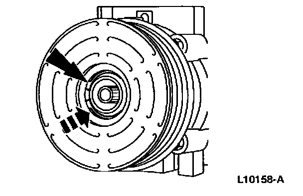
4. Install the pulley snap ring with the bevel side out.
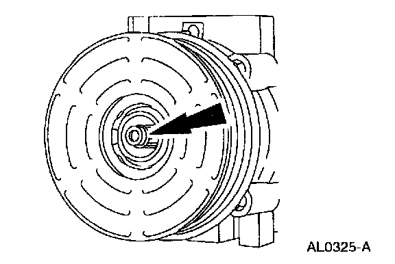
5. Place one nominal thickness A/C clutch hub spacer inside the clutch hub spline opening.
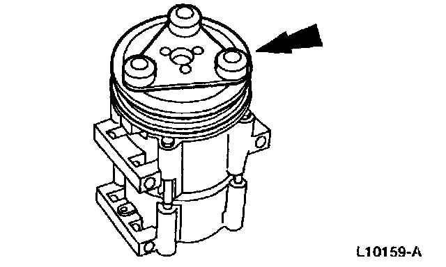
6. Install the A/C clutch.
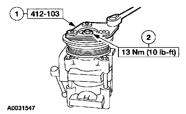
7. Install the A/C clutch hub retaining bolt.
1 Hold the A/C clutch hub with the special tool.
2 Tighten the bolt.
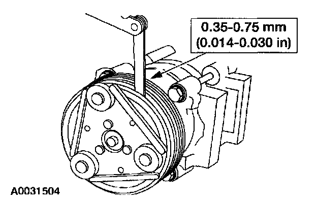
8. Measure and adjust the clutch air gap by removing or adding the A/C clutch hub spacer.
9. Install the A/C compressor.
Factory Service Tools
Use the Manual With the Right Hardware
Pair factory procedures with proven DIY tools so the instructions are easier to execute.
Disclosure: Verified tool recommendations may earn an affiliate commission at no cost to you.
When to See a Mechanic
Stop DIY work and contact a certified mechanic immediately if any of the following apply:
- • You smell fuel, burning insulation, or see smoke.
- • Brakes feel soft, pull hard to one side, or make grinding noises.
- • The engine overheats, stalls repeatedly, or misfires under load.
- • You are missing required tools, torque specs, or safe lifting equipment.
- • You are not confident in the next step or safety outcome.