
Safety Warning
DIY auto repair can cause serious injury, fire, or vehicle damage. These guides are for informational purposes only. Always follow OEM torque specs, wear PPE, and consult a certified mechanic if you are unsure. You are solely responsible for your safety.
2012 Chrysler 300 AWD V8-5.7LFACTORY OEM SERVICE PROCEDURE
Distance Sensor: Adjustments
STANDARD PROCEDURE - ACC SENSOR ALIGNMENT
Special Tools:
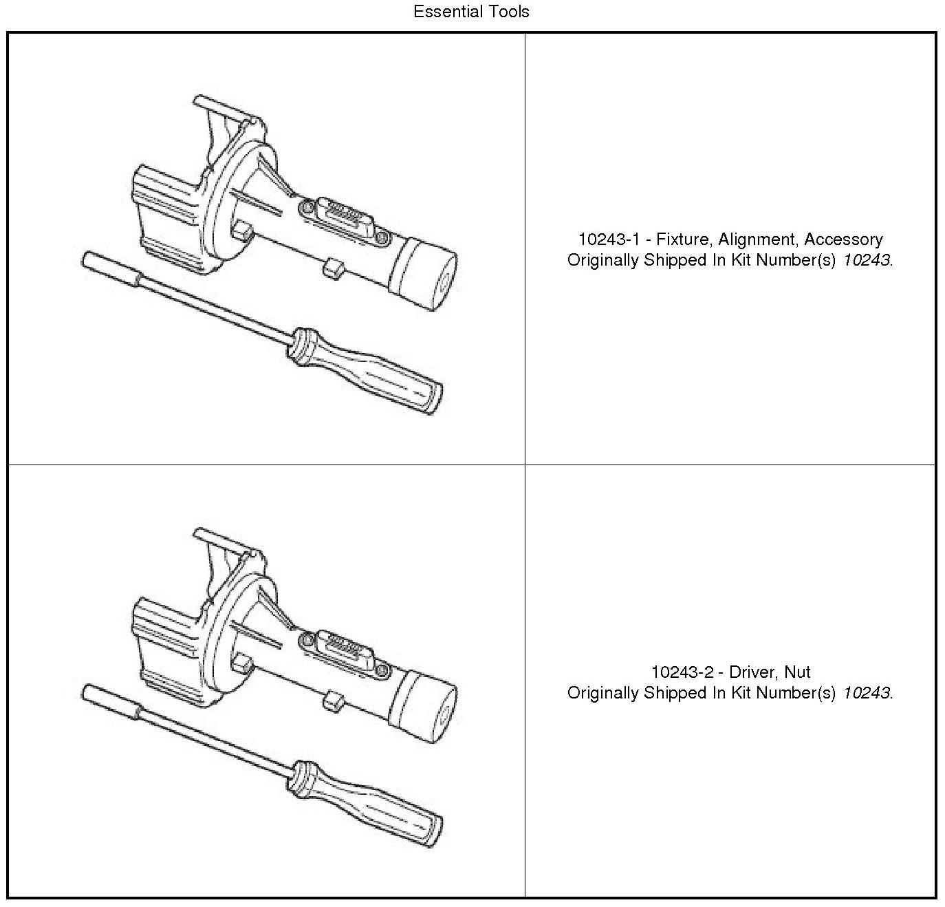
The adaptive speed control sensor (also known as the Adaptive Cruise Control/ACC sensor or module, or the radar sensor or module) requires alignment whenever the ACC sensor is removed and reinstalled, whenever front end structural repairs are performed or whenever a Diagnostic Trouble Code (DTC) indicates ACC sensor adjustment is required. Sensor alignment consists of performing the mechanical vertical alignment described in the following procedure, followed by the electronic horizontal alignment that is performed with a diagnostic scan tool and the appropriate diagnostic information during a 10 minute drive while maintaining a steady, predetermined vehicle speed.
VEHICLE PREPARATION FOR SENSOR VERTICAL ALIGNMENT
1. Repair or replace any ineffective, worn or damaged body or suspension components that could hinder proper sensor alignment.
2. Verify proper tire inflation pressures.
3. Remove any accumulations of mud, snow or ice from the vehicle underbody.
4. Verify that there is no load in the vehicle (cargo or passengers), except for the driver.
5. The fuel tank should be FULL. Add 2.94 kilograms (6.5 pounds) of weight over the fuel tank for each estimated gallon of missing fuel.
6. Verify correct vehicle suspension height.
NOTE: The vehicle MUST be placed on a known level horizontal surface such as a wheel or frame alignment rack to achieve satisfactory sensor vertical alignment results.
7. Rock the vehicle side-to-side three times to allow the suspension to stabilize.
8. Jounce the front suspension three times by pushing downward on the front bumper and releasing.
SENSOR VERTICAL ALIGNMENT
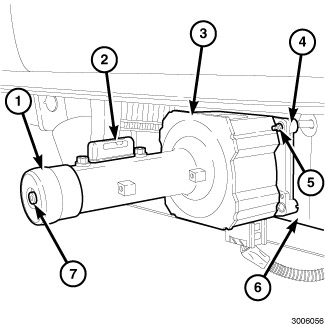
1. The adaptive speed control sensor (4) (also known as the Adaptive Cruise Control/ACC sensor or module and the radar sensor or module) is located on a bracket (6) secured near the right frame rail on the underside of the front bumper support member of the Front End Module (FEM) behind the front fascia.
2. Remove the front fascia from the vehicle. Front Bumper Fascia - Removal.
3. If equipped, unsnap the plastic bezel (mirror cover) from over the front of the sensor housing.
4. Clean any dirt or road salt from the convex molded dark plastic lens (radar dome) on the face of the sensor as well as from the suction cup of the (10243-1) (3).
5. Carefully slide the vertical alignment tool over the sensor housing until the suction cup rests against the lens of the sensor.
6. Depress the plunger (1) of the vertical alignment tool to engage the suction cup and attach the special tool securely to the lens of the sensor.
7. Use the 3.5 millimeter (10243-2) to rotate the two adjustable ball studs (5) that secure the sensor to the mounting bracket as necessary to center the bubble of the spirit level (2) between the two center marks on the vial of the level located on the top of the vertical alignment tool.
8. Depress the center release button (7) to release the suction cup from the sensor lens and remove the special tool from the sensor.
9. If equipped, reinstall the plastic bezel (mirror cover) over the front of the sensor housing.
10. Reinstall the front fascia onto the vehicle. Front Bumper Fascia - Installation.
11. Use a diagnostic scan tool and the appropriate diagnostic information to perform the horizontal sensor alignment procedure.
Factory Service Tools
Use the Manual With the Right Hardware
Pair factory procedures with proven DIY tools so the instructions are easier to execute.
Disclosure: Verified tool recommendations may earn an affiliate commission at no cost to you.
When to See a Mechanic
Stop DIY work and contact a certified mechanic immediately if any of the following apply:
- • You smell fuel, burning insulation, or see smoke.
- • Brakes feel soft, pull hard to one side, or make grinding noises.
- • The engine overheats, stalls repeatedly, or misfires under load.
- • You are missing required tools, torque specs, or safe lifting equipment.
- • You are not confident in the next step or safety outcome.