
Safety Warning
DIY auto repair can cause serious injury, fire, or vehicle damage. These guides are for informational purposes only. Always follow OEM torque specs, wear PPE, and consult a certified mechanic if you are unsure. You are solely responsible for your safety.
2012 Chrysler 300 AWD V6-3.6LFACTORY OEM SERVICE PROCEDURE
Fuel Pump Module - Installation
INSTALLATION
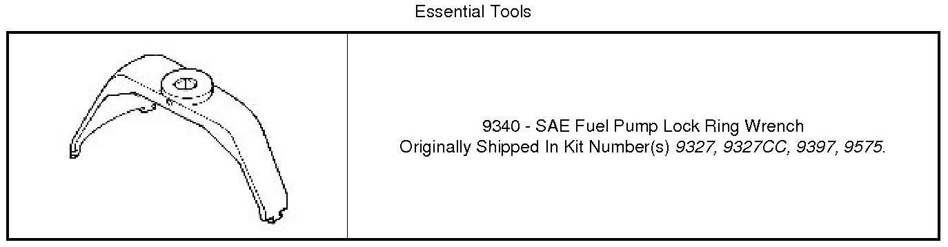
Special Tools:
MAIN FUEL PUMP MODULE
WARNING: No sparks, open flames or smoking. Risk of poisoning from inhaling and swallowing fuel. Pour fuel only into appropriately marked OSHA approved containers. Wear protective clothing. Risk of injury to eyes and skin from contact with fuel.
CAUTION: Do not allow the float arm of the Main Fuel Pump Module to come in contact with any part of the fuel tank during removal or installation, damage to the float arm and fuel level sending card may result.
NOTE: The Auxiliary Fuel Pump Module must be installed before the Main Fuel Pump Module.
1. If the auxiliary fuel pump module is removed, see AUXILIARY FUEL PUMP MODULE.
NOTE: Whenever the fuel pump module is serviced, the rubber O-ring seal must be replaced.
2. Install a new rubber O-ring seal.
3. Using caution not to bend the float arm, lower the bottom section of the main fuel pump module into the fuel tank.
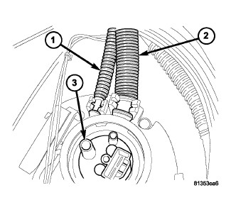
4. Connect the fuel return lines (1,2) to the main fuel pump module.
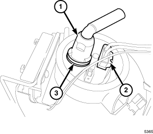
5. Connect the fuel supply line (1) to the main fuel pump module.
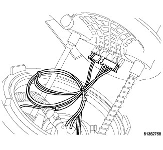
6. Connect the electrical connectors at the top section of the main fuel pump module.
7. Join the upper section and lower section of the main fuel pump module together.
8. Position the main fuel pump module as noted during removal.
CAUTION: Verify the electrical wires are tucked away into the fuel tank so they don't get pinched between the top of the fuel pump module and the rubber O-ring seal.
CAUTION: An indexing arrow is located on top of the fuel pump module to clock it's position into the fuel tank. The fuel pump module must be installed in the same position as removed.
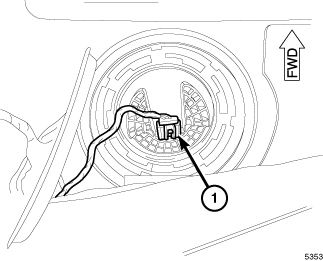
9. Align the rubber O-ring seal and lower the main fuel pump module into position.
10. Verify the main fuel pump module is in the same position as noted during removal. This step must be performed to prevent the float from contacting the side of the fuel tank.
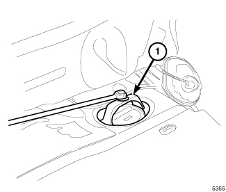
11. Position the lock ring over top of the main fuel pump module.
12. Position the SAE Fuel Pump Lock Ring Wrench (1) into the notches on the outside edge of the lock ring.
13. Install a 1/2 inch drive breaker bar into the SAE Fuel Pump Lock Ring Wrench.
14. Rotate the breaker bar clockwise until all seven notches of the lock ring have engaged.
15. Connect the electrical connector (1) to the main fuel pump module.
16. Fill the fuel tank and check for leaks around the rubber O-ring seal.
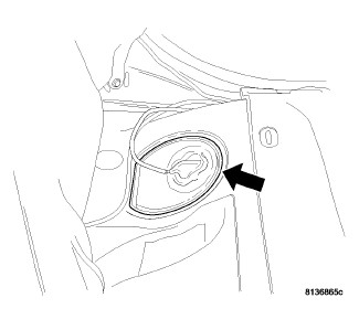
17. Install the main fuel pump module plastic access cover.
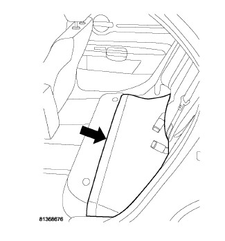
18. Lower the foam pad covering back into place.
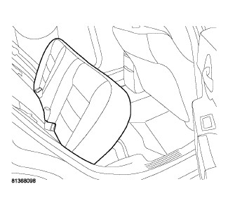
19. Push the rear lower seat cushion back and down and install the seat cushion.
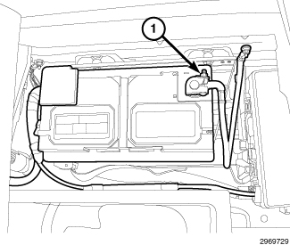
20. Connect the negative battery cable.
AUXILIARY FUEL PUMP MODULE
CAUTION: An indexing arrow is located on top of the fuel pump module to clock it's position into the fuel tank. The fuel pump module must be installed in the same position as removed.
CAUTION: Do not allow the float arm of the Auxiliary Fuel Pump Module to come in contact with any part of the fuel tank during removal or installation, damage to the float arm and fuel level sending card may result.
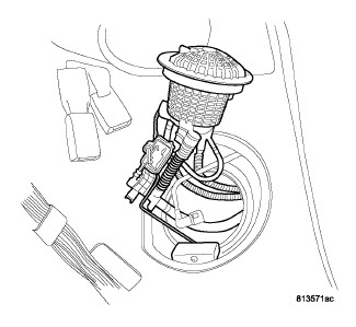
NOTE: Whenever the fuel pump module is serviced, the rubber O-ring seal must be replaced.
1. Install a new rubber O-ring seal.
2. Using caution not to bend the float arm, lower the auxiliary fuel pump module into the fuel tank while guiding the fuel return lines, fuel supply line and electrical connector over to the left side of the fuel tank.
3. Align the rubber O-ring seal and lower the auxiliary fuel pump module into position as noted during removal.
4. Position the lock ring over top of the auxiliary fuel pump module.
5. Verify the auxiliary fuel pump module is in the same position as noted during removal. This step must be performed to prevent the float from contacting the side of the fuel tank.
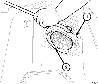
6. Position the SAE Fuel Pump Lock Ring Wrench (1) into the notches on the outside edge of the lock ring (2).
7. Install a 1/2 inch drive breaker bar into the SAE Fuel Pump Lock Ring Wrench (1).
8. Rotate the breaker bar clockwise until all seven notches of the lock ring have engaged.
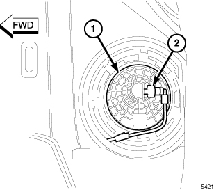
9. Connect the fuel supply line (2) to auxiliary fuel pump module (1).
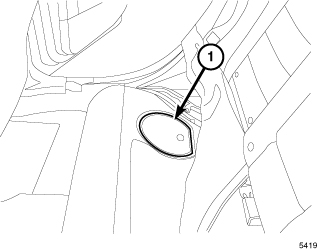
10. Install the auxiliary fuel pump module plastic access cover (1).
11. Install the main fuel pump module, see MAIN FUEL PUMP MODULE.
Factory Service Tools
Use the Manual With the Right Hardware
Pair factory procedures with proven DIY tools so the instructions are easier to execute.
Disclosure: Verified tool recommendations may earn an affiliate commission at no cost to you.
When to See a Mechanic
Stop DIY work and contact a certified mechanic immediately if any of the following apply:
- • You smell fuel, burning insulation, or see smoke.
- • Brakes feel soft, pull hard to one side, or make grinding noises.
- • The engine overheats, stalls repeatedly, or misfires under load.
- • You are missing required tools, torque specs, or safe lifting equipment.
- • You are not confident in the next step or safety outcome.