
Safety Warning
DIY auto repair can cause serious injury, fire, or vehicle damage. These guides are for informational purposes only. Always follow OEM torque specs, wear PPE, and consult a certified mechanic if you are unsure. You are solely responsible for your safety.
2008 Chrysler Crossfire V6-3.2LFACTORY OEM SERVICE PROCEDURE
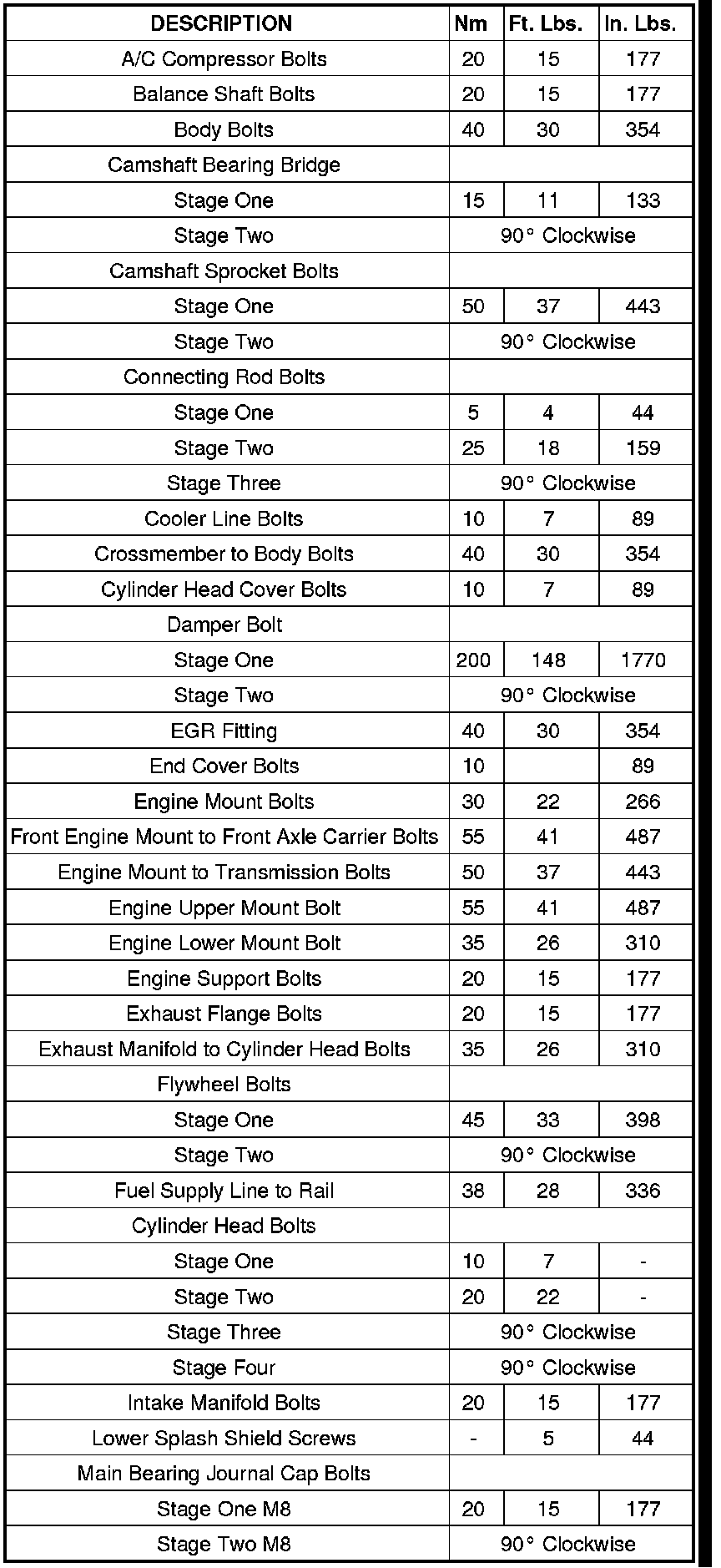
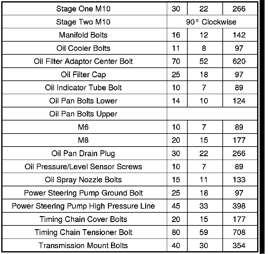
Engine Torque Specifications
TORQUE SPECIFICATIONS
CYLINDER HEAD TORQUE AND SEQUENCE
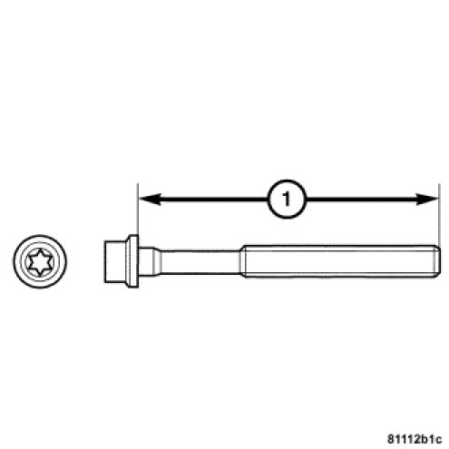
NOTE: Measure and inspect cylinder head bolts before reuse. Do not reuse bolts that exceed 144 mm (1) in length.
NOTE: Apply a thin coat of lubricant to head bolt threads before installing.
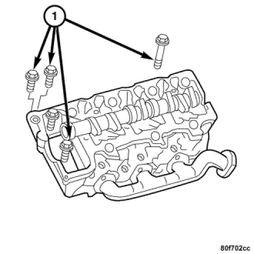
1. Install, but do not tighten the cylinder head bolts (1).
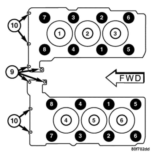
2. Use the tightening sequence chart to tighten the cylinder head bolts.
NOTE: Bolts numbered 9 and 10 are timing chain cover bolts. They should be tightened after the cylinder head bolts are tightened.
3. Tighten the cylinder head bolts in four stages.
- Stage one, 10 Nm (7 ft. lbs.)
- Stage two, 30 Nm (22 ft. lbs.)
- Stage three, Rotate bolts 90° clockwise.
- Stage four Rotate bolts 90° clockwise.
- Tighten bolts 9 and 10 to 20 Nm (7-15 ft. lbs.).
INTAKE MANIFOLD TORQUE
Intake manifold bolts 20 Nm (15 ft. lbs.)
CAMSHAFT BEARING BRIDGE
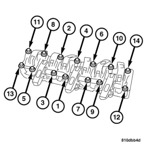
1. Install, but do not tighten the bearing bridge bolts.
2. Tighten the M7 45 (short) bolts to 15 Nm (11 ft. lbs) and the M7 84 (long) bolts to 10 Nm (8 ft. lbs) in the sequence shown above.
3. Continue to tighten only the M7 84 (long) bolts in the sequence shown an additional 90° clockwise. Skipping M7 45 bolts (short bolts) this time.
MAIN BEARING CAP TORQUE AND SEQUENCE
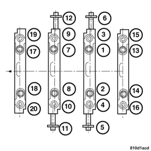
1. Follow the torque sequence shown for the crankshaft main bearing journal cap bolts.
2. Main bearing journal caps must be tightened in two stages.
- Stage one for m8 bolts, 20 Nm (15 ft. lbs.).
- Stage two for m8 bolts, rotate 90° clockwise.
- Stage one for m10 bolts, 30 Nm (22 ft. lbs.).
- Stage two for m10 bolts, rotate 90° clockwise.
3. Turn the crankshaft to check for unobstructed movement.
ROD BEARING CAP TORQUE
Tighten the connecting rod bolts in three stages.
- Stage one, 5 Nm (44 in. lbs.)
- Stage two, 25 Nm (18 ft. lbs.)
- Stage three, rotate bolts 90° clockwise.
HARMONIC BALANCER TORQUE
1. Measure the vibration damper bolt. Replace the bolt if length exceeds 78 mm.
2. Position the vibration damper on the front of the crankshaft.
3. Lubricate the bolt threads with engine oil before installing.
4. Install the vibration damper bolt and tighten:
- 1st to 200 Nm (148 ft. lbs.),
- Then retighten the bolt an additional 90° clockwise.
FLYWHEEL TORQUE AND SEQUENCE
Initially tighten the flywheel bolts to 45 Nm (33 ft. lbs.). For final torque, rotate the flywheel bolts an additional 45° clockwise using a torque angle gauge.
FLYWHEEL TORQUE
NOTE: New flywheel/flexplate bolts must be used.
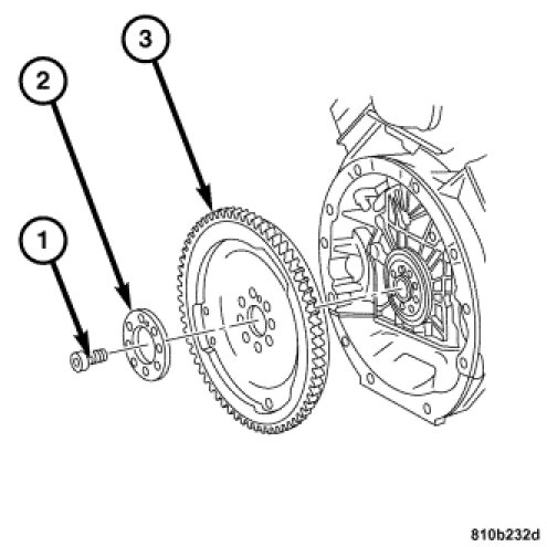
1. Install the spacer and new flywheel/flexplate bolts (1). Tighten bolts to 45 Nm (33 ft. lbs.)
2. Rotate the flywheel/flexplate bolts an additional 90° clockwise.
OIL PUMP TORQUE
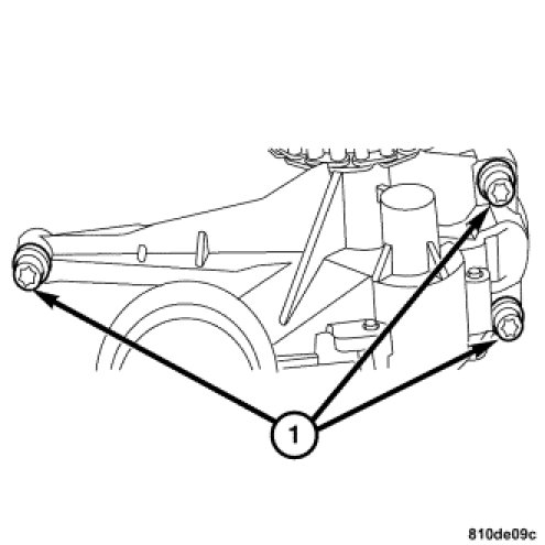
Oil pump 20 Nm (15 ft. lbs.)
EXHAUST MANIFOLD TORQUE
Exhaust manifold 35 Nm (26 ft. lbs.)
WATER PUMP TORQUE
Water pump 35 Nm (26 ft. lbs.)
Factory Service Tools
Use the Manual With the Right Hardware
Pair factory procedures with proven DIY tools so the instructions are easier to execute.
Disclosure: Verified tool recommendations may earn an affiliate commission at no cost to you.
When to See a Mechanic
Stop DIY work and contact a certified mechanic immediately if any of the following apply:
- • You smell fuel, burning insulation, or see smoke.
- • Brakes feel soft, pull hard to one side, or make grinding noises.
- • The engine overheats, stalls repeatedly, or misfires under load.
- • You are missing required tools, torque specs, or safe lifting equipment.
- • You are not confident in the next step or safety outcome.