
Safety Warning
DIY auto repair can cause serious injury, fire, or vehicle damage. These guides are for informational purposes only. Always follow OEM torque specs, wear PPE, and consult a certified mechanic if you are unsure. You are solely responsible for your safety.
2008 Chrysler Crossfire V6-3.2LFACTORY OEM SERVICE PROCEDURE
System Specifications
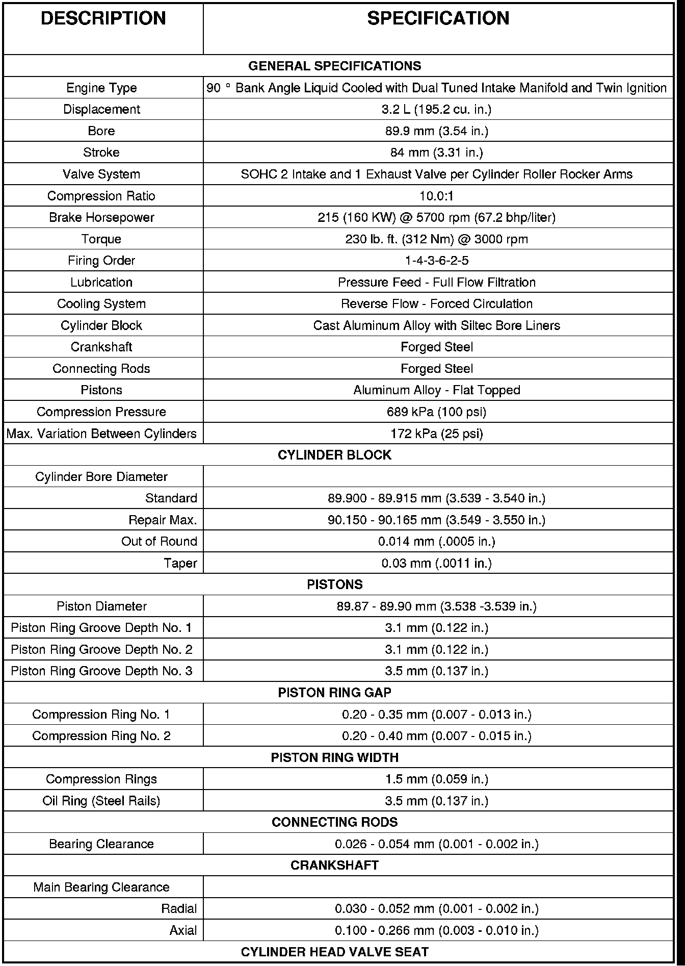
ENGINE SPECIFICATIONS
CYLINDER HEAD FLATNESS INSPECTION
Deck surface must be within service limit 0.004 in. (0.1 mm).
MAIN BEARING CAP TORQUE AND SEQUENCE
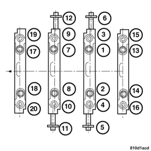
1. Follow the torque sequence shown for the crankshaft main bearing journal cap bolts.
2. Main bearing journal caps must be tightened in two stages.
- Stage one for m8 bolts, 20 Nm (15 ft. lbs.).
- Stage two for m8 bolts, rotate 90° clockwise.
- Stage one for m10 bolts, 30 Nm (22 ft. lbs.).
- Stage two for m10 bolts, rotate 90° clockwise.
3. Turn the crankshaft to check for unobstructed movement.
HARMONIC BALANCER TORQUE
1. Measure the vibration damper bolt. Replace the bolt if length exceeds 78 mm.
2. Position the vibration damper on the front of the crankshaft.
3. Lubricate the bolt threads with engine oil before installing.
4. Install the vibration damper bolt and tighten:
- 1st to 200 Nm (148 ft. lbs.),
- Then retighten the bolt an additional 90° clockwise.
MAIN BEARING SIZE CODE CHARTS
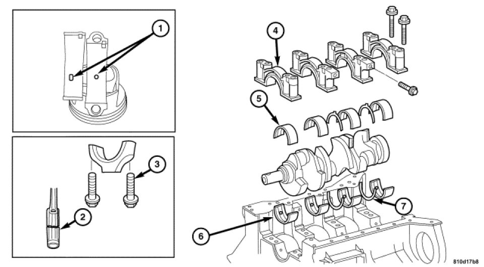
NOTE: Before the Crankshaft can be installed, the proper thickness upper and lower main bearings along with the proper thickness thrust plate have to be selected. Below are tables followed by directions to help you determine the appropriate thickness upper and lower main bearing shell halves and thrush plate.
UPPER BEARING SHELL SELECTION

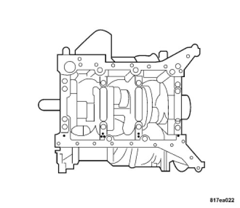
The top bearing shell halves are assigned to the specific journal of the crankshaft by means of a colored ring on the rear of the upper bearing shell half and numbers or center punch marks, which are stamped into the crankcase near the bearing cap. Only the assigned color and numerical combinations may be fitted together. EXAMPLE: You see the number 2 or two punch marks stamped into the cylinder block, you need to use the Yellow bearing shell half for the upper bearing shell.
LOWER BEARING SHELL SELECTION
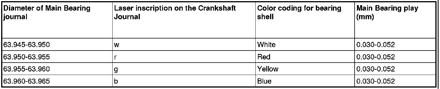
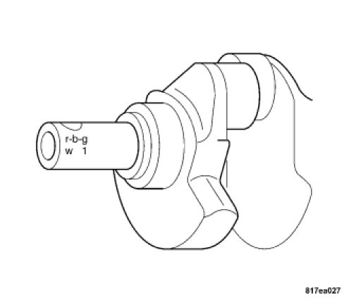
The bottom halves of the bearing shells are assigned to the specific journal of the crankshaft by means of a letter engraved on the journal of the crankshaft. Each letter represents a color of the necessary bearing shell. EXAMPLE: If the first letter engraved on the crankshaft is a "r", than the first lower main bearing shell half is the Red main bearing shell half.
CYLINDER HEAD FLATNESS INSPECTION
Deck surface must be within service limit 0.004 in. (0.1 mm).
MAIN BEARING CAP TORQUE AND SEQUENCE
1. Follow the torque sequence shown for the crankshaft main bearing journal cap bolts.
2. Main bearing journal caps must be tightened in two stages.
- Stage one for m8 bolts, 20 Nm (15 ft. lbs.).
- Stage two for m8 bolts, rotate 90° clockwise.
- Stage one for m10 bolts, 30 Nm (22 ft. lbs.).
- Stage two for m10 bolts, rotate 90° clockwise.
3. Turn the crankshaft to check for unobstructed movement.
HARMONIC BALANCER TORQUE
1. Measure the vibration damper bolt. Replace the bolt if length exceeds 78 mm.
2. Position the vibration damper on the front of the crankshaft.
3. Lubricate the bolt threads with engine oil before installing.
4. Install the vibration damper bolt and tighten:
- 1st to 200 Nm (148 ft. lbs.),
- Then retighten the bolt an additional 90° clockwise.
MAIN BEARING SIZE CODE CHARTS
NOTE: Before the Crankshaft can be installed, the proper thickness upper and lower main bearings along with the proper thickness thrust plate have to be selected. Below are tables followed by directions to help you determine the appropriate thickness upper and lower main bearing shell halves and thrush plate.
UPPER BEARING SHELL SELECTION
The top bearing shell halves are assigned to the specific journal of the crankshaft by means of a colored ring on the rear of the upper bearing shell half and numbers or center punch marks, which are stamped into the crankcase near the bearing cap. Only the assigned color and numerical combinations may be fitted together. EXAMPLE: You see the number 2 or two punch marks stamped into the cylinder block, you need to use the Yellow bearing shell half for the upper bearing shell.
LOWER BEARING SHELL SELECTION
The bottom halves of the bearing shells are assigned to the specific journal of the crankshaft by means of a letter engraved on the journal of the crankshaft. Each letter represents a color of the necessary bearing shell. EXAMPLE: If the first letter engraved on the crankshaft is a "r", than the first lower main bearing shell half is the Red main bearing shell half.
Factory Service Tools
Use the Manual With the Right Hardware
Pair factory procedures with proven DIY tools so the instructions are easier to execute.
Disclosure: Verified tool recommendations may earn an affiliate commission at no cost to you.
When to See a Mechanic
Stop DIY work and contact a certified mechanic immediately if any of the following apply:
- • You smell fuel, burning insulation, or see smoke.
- • Brakes feel soft, pull hard to one side, or make grinding noises.
- • The engine overheats, stalls repeatedly, or misfires under load.
- • You are missing required tools, torque specs, or safe lifting equipment.
- • You are not confident in the next step or safety outcome.