
Safety Warning
DIY auto repair can cause serious injury, fire, or vehicle damage. These guides are for informational purposes only. Always follow OEM torque specs, wear PPE, and consult a certified mechanic if you are unsure. You are solely responsible for your safety.
2008 Chrysler Crossfire V6-3.2LFACTORY OEM SERVICE PROCEDURE
Power Door Lock Control Module
Component ID: 48
Component : CENTRAL LOCKING PUMP/SECURITY SYSTEM MODULE
Connector:
Name : CENTRAL LOCKING PUMP/SECURITY SYSTEM MODULE C1
Color : WHITE
# of pins : 18
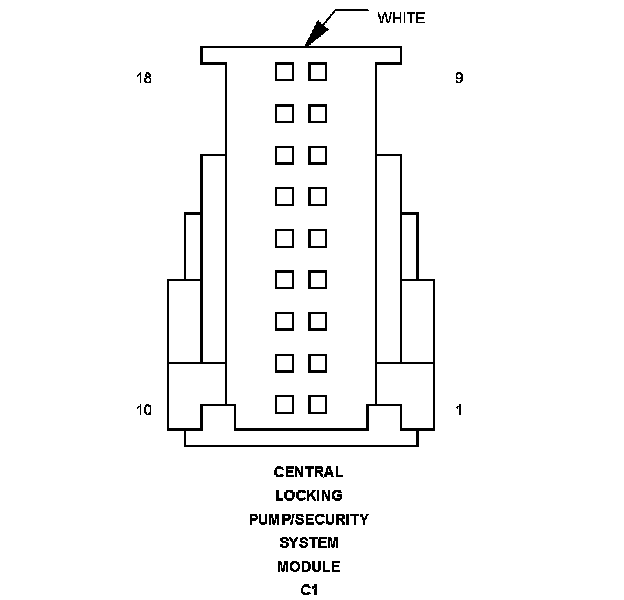
Pin Circuit Description
1 - -
2 - -
3 - -
4 - -
5 - -
6 - -
7 - -
8 20WT CAN B BUS (+)
8 22WT CAN B BUS (+)
9 20DG CAN B BUS (-)
9 22DG CAN B BUS (-)
10 - -
11 - -
12 - -
13 20BR/BL LIFTGATE LOCK SWITCH SENSE (UNLOCK)
13 20BR/YL LIFTGATE LOCK SWITCH SENSE (UNLOCK)
14 20BR/GY LEFT DOOR AJAR SWITCH SENSE
15 - -
16 20BR/PK RIGHT DOOR AJAR SWITCH SENSE
17 - -
18 - -
Component Location - 22
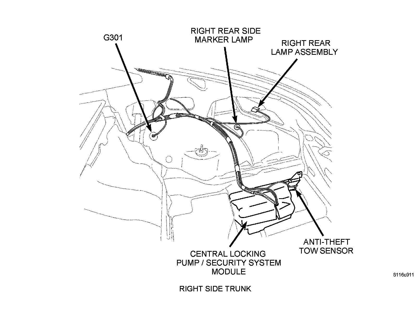
Component Location - 1
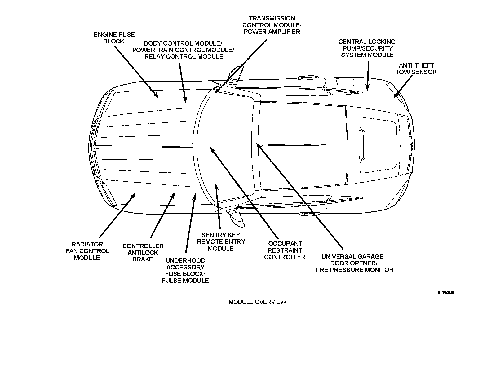
Connector:
Name : CENTRAL LOCKING PUMP/SECURITY SYSTEM MODULE C2
Color : BLACK
# of pins : 4
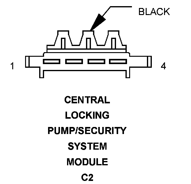
Pin Circuit Description
1 14BK REAR WINDOW DEFOGGER GRID SUPPLY
2 12RD/DG FUSED B(+)
3 14BR GROUND
4 16BK/YL/WT FUSED B(+)
Component Location - 22
Component Location - 1
Connector:
Name : CENTRAL LOCKING PUMP/SECURITY SYSTEM MODULE C3
Color : BLACK
# of pins : 18
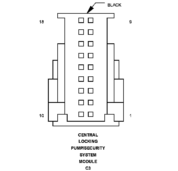
Pin Circuit Description
1 - -
2 - -
3 - -
4 22DG/GY SENSOR GROUND
5 18BR/RD HOOD AJAR SWITCH SENSE
6 20WT/DG TOW-AWAY ALARM SWITCH SENSE
7 20YL/RD SIREN SIGNAL OUTPUT
8 20YL INTRUSION SENSOR SIGNAL
9 20BR/DG TONNEAU COVER SWITCH SENSE
10 - -
11 22RD/DG TOW-AWAY ALARM SWITCH LED CONTROL
12 - -
13 - -
14 - -
15 18BR/DG ANTI-THEFT TOW SENSOR SIGNAL
16 20BR/GY GLOVE BOX SWITCH SENSE
17 - -
18 - -
Component Location - 22
Component Location - 1
Connector:
Name : CENTRAL LOCKING PUMP/SECURITY SYSTEM MODULE C4
Color : BLACK
# of pins : 4
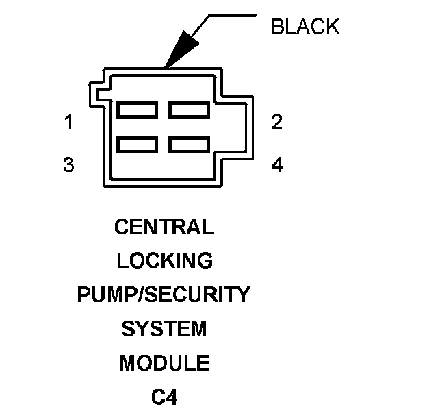
Pin Circuit Description
1 14YL/BK FOG LAMP SWITCH OUTPUT
2 18GY/RD RIGHT TAIL LAMP OUTPUT
2 18BK/DG RIGHT TAIL LAMP OUTPUT
3 - -
4 18GY/BK LEFT TAIL LAMP OUTPUT
4 18BK/WT LEFT TAIL LAMP OUTPUT
Component Location - 22
Component Location - 1
Factory Service Tools
Use the Manual With the Right Hardware
Pair factory procedures with proven DIY tools so the instructions are easier to execute.
Disclosure: Verified tool recommendations may earn an affiliate commission at no cost to you.
When to See a Mechanic
Stop DIY work and contact a certified mechanic immediately if any of the following apply:
- • You smell fuel, burning insulation, or see smoke.
- • Brakes feel soft, pull hard to one side, or make grinding noises.
- • The engine overheats, stalls repeatedly, or misfires under load.
- • You are missing required tools, torque specs, or safe lifting equipment.
- • You are not confident in the next step or safety outcome.