
Safety Warning
DIY auto repair can cause serious injury, fire, or vehicle damage. These guides are for informational purposes only. Always follow OEM torque specs, wear PPE, and consult a certified mechanic if you are unsure. You are solely responsible for your safety.
2003 Chevrolet Express 1/2 Ton Van V6-4.3L VIN XFACTORY OEM SERVICE PROCEDURE
Key & Lock Cylinder Coding
Key and Lock Cylinder Coding
Key Identification and Usage
The lock cylinder keyway is designed so that other model keys will not enter a current model lock cylinder. A single key is used for all locks on the vehicle.
The key identification is obtained from the four-character key code stamped on the knockout portion of the key head. Knock the plugs out of the key head after code numbers have been recorded. The code list, available to owners of key cutting equipment from equipment suppliers, determines the lock combinations from the code numbers.
Cutting Keys
After the code has been determined from the code list or the key code diagram, perform the following steps:
1. Cut a blank key to the proper level of each of the tumbler positions.
2. Inspect the key operation in the lock cylinder.
Replacement Lock Cylinders
New lock cylinders (except ignition lock cylinders) are available from the service parts warehouse with new lock cylinder locking bars. The tumblers are also available and must be assembled into the cylinder as recommended. For additional information, refer to the following.
Lock Cylinder Tumbler Operation
All lock tumblers are shaped alike with the exception of the notched position on one side. As the key is inserted into the lock cylinder, the tumblers are lowered to the correct height so that notches on each tumbler are at the same level. When the notches on all six tumblers line up, two small springs push the side bar into the notches, allowing the cylinder to turn in the cylinder bore. Five types of tumblers are used in making the lock combinations, and each is coded and stamped with a number between 1 and 5.
Assembling and Coding Ignition Lock Cylinders
Tools Required
J 41340 Ignition Lock Holding Fixture
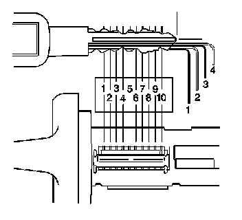
1. Determine the tumbler numbers/arrangement:
1. Place the tip of the key directly over the tip of the illustrated key.
2. Inspect that the diagram outlines the key.
3. Starting with position 1 (open end of cylinder), find and record the lowest level (tumbler number) that is visible.
4. Repeat the previous step for positions 2-10.
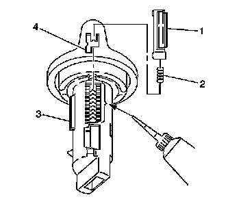
2. Starting with position 1, insert the tumblers (4) into their corresponding slots in the coded order.
3. Using your fingers, pull out the side bar (3) until the tumblers fall completely into place.
4. Insert one tumbler spring (2) above each tumbler (4).
5. Lubricate the tumblers using Superlube(R) GM P/N 12346241 or equivalent.
6. Insert the spring retainer (1) prongs into the slots at the end of each cylinder.
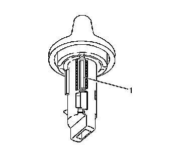
7. Press down the retainer (1) until fully seated in the depression.
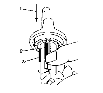
8. Inspect for proper tumbler installation:
1. Hold the spring retainer (2) in position.
2. Insert the key (1) into the cylinder.
3. The side bar (3) should drop down flush with the cylinder diameter if properly installed.
4. Disassemble and assemble properly as needed.
9. Remove the key.
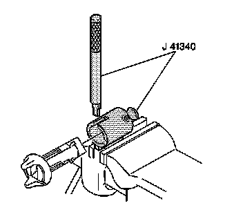
10. Secure the cylinder in the J 41340 .
1. Inspect that the spring retainer is facing up and positioned directly under the punch slots.
2. Push the cylinder into the J 41340 until butted with the cylinder bezel.
3. Tighten the holding screw.
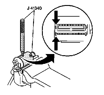
11. Stake the bezel end of the retainer in place:
1. Hold the flat side of the punch, part of J 41340 , squarely against the face of the cylinder bezel.
2. Stake the lock cylinder metal over the retainer corners.
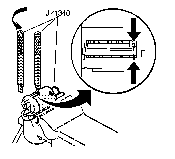
12. Stake the other end of the retainer:
1. Remove the punch, part of J 41340 .
2. Rotate the punch, part of J 41340 , 180 degrees.
3. Hold the punch, part of J 41340 , squarely against the end of the punch slot on J 41340 .
4. Stake the metal over the other end of the retainer.
13. Loosen the holding screw.
14. Remove the cylinder from the J 41340 .
15. Inspect that the retainer is properly staked. Restake as needed.
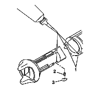
16. Lubricate the cylinder retainer slot.
17. Insert the following parts into the cylinder retainer slot:
* The retainer spring (2)
* The retainer (3)
Important: Use a paste type grease, not a spray, for the following step.
18. Lubricate the following parts with GM P/N 12345996 or equivalent as needed:
* The detent pins (1)
* The cylinder retainer (3)
Side Door Lock Cylinder Coding
The side door lock cylinder has five snap-in tumblers. The number 1-5 positions (beginning closest to the cylinder head) is a brass retainer tumbler. The 6-10 positions are standard tumbler positions. Therefore, only the 6-10 positions are required.
Factory Service Tools
Use the Manual With the Right Hardware
Pair factory procedures with proven DIY tools so the instructions are easier to execute.
Disclosure: Verified tool recommendations may earn an affiliate commission at no cost to you.
When to See a Mechanic
Stop DIY work and contact a certified mechanic immediately if any of the following apply:
- • You smell fuel, burning insulation, or see smoke.
- • Brakes feel soft, pull hard to one side, or make grinding noises.
- • The engine overheats, stalls repeatedly, or misfires under load.
- • You are missing required tools, torque specs, or safe lifting equipment.
- • You are not confident in the next step or safety outcome.
Rather have a pro handle this?
A certified mobile mechanic comes to your home or office. They bring the tools, you stay comfortable. No tow truck, no waiting room, no surprises.
Comes to youSame-day available12-month warranty
Get a Free QuoteNo obligation. See pricing before you book.