B1283

Factory Manual References

Factory service manual diagnostic procedure for 2012 acura zdx

A L L Diagnostic Trouble Codes ( DTC )

B1281


DTC Troubleshooting: B1281, B1282, B1283, B1284

DTC B1281:

Front Wiper MIST Position Circuit Malfunction

DTC B1282:

Front Wiper INT (AUTO) Position Circuit Malfunction

DTC B1283:

Front Wiper LOW Position Circuit Malfunction

DTC B1284:

Front Wiper HIGH Position Circuit Malfunction

NOTE: If you are troubleshooting multiple DTCs, be sure to follow the instructions in B-CAN System Diagnosis Test Mode A Troubleshooting - B-CAN System Diagnosis Test Mode A.

1. Clear the DTCs with the HDS.

2. Turn the ignition switch to LOCK (0), and then back to ON (II), or press the engine start/stop button to select the OFF mode and then the ON mode.

3. Turn the wiper switch to the MIST, INT, LOW, HIGH, and OFF positions.

4. Wait for at least 6 seconds.

5. Check for DTCs with the HDS.

Are DTCs B1281, B1282, B1283, and/or B1284 indicated?

YES -

Go to step 6.

NO -

Intermittent failure, the wiper system is OK at this time. Check for loose or poor connections.

6. Select WIPER from the BODY ELECTRICAL SYSTEM SELECT menu, and enter the DATA LIST.

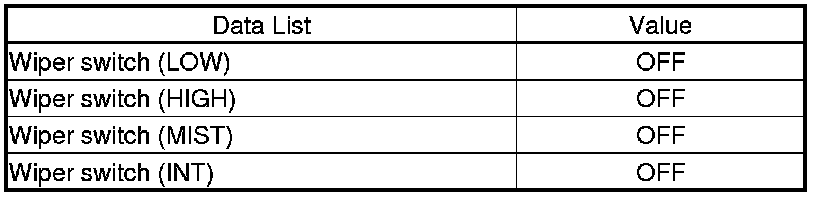
7. Check each wiper switch position value with the DATA LIST menu.

When the wiper switch is turned OFF

Factory service manual diagram


Are all data list values correct?

YES -

Go to step 8.

NO -

Go to step 11.

8. Turn the ignition switch to LOCK (0), or press the engine start/stop button to select the OFF mode.

9. Disconnect driver's under-dash fuse/relay box connector R (24P).

10. Check for continuity between driver's under-dash fuse/relay box connector R (24P) terminals as shown:

Factory service manual diagram


Is there continuity?

YES -

Repair short between the wires.

NO -

Faulty driver's MICU; replace the driver's under-dash fuse/relay box Drivers Under-Dash Fuse/Relay Box (Drivers MICU) Removal and Installation.

11. Turn the ignition switch to LOCK (0), or press the engine start/stop button to select the OFF mode.

12. Disconnect the 8P connector from the wiper switch.

13. Turn the ignition switch to ON (II), or press the engine start/stop button to select the ON mode.

14. Check each wiper switch position value with the DATA LIST menu.

Factory service manual diagram


Are all data list values correct?

YES -

Replace the wiper/washer switch Service and Repair.

NO -

Go to step 15.

15. Turn the ignition switch to LOCK (0), or press the engine start/stop button to select the OFF mode.

16. Disconnect driver's under-dash fuse/relay box connector R (24P).

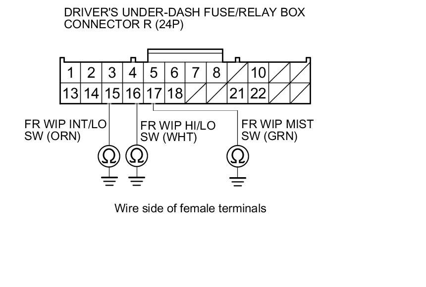
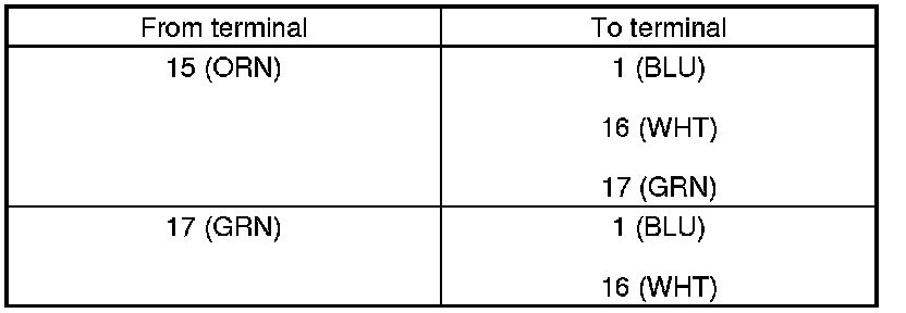
17. Check for continuity between body ground and driver's under-dash fuse/relay box connector R (24P) terminals No. 15,No. 16, and No. 17 individually.

Factory service manual diagram


Is there continuity?

YES -

Repair a short to ground in the wire(s).

NO -

Go to step 18.

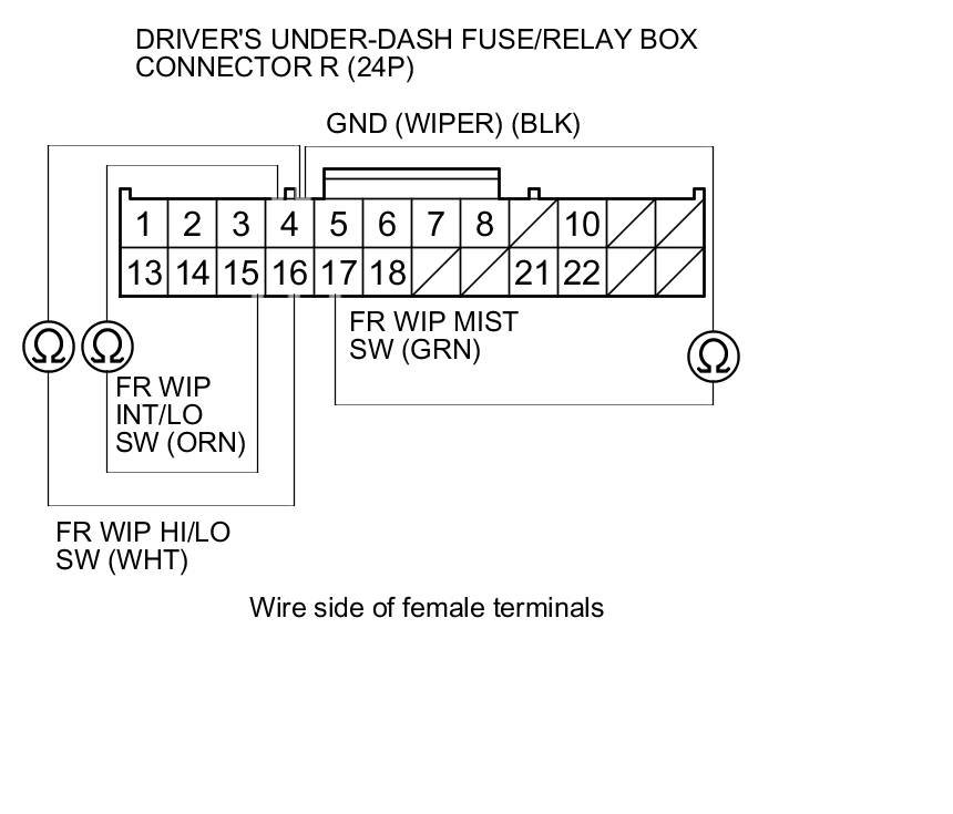
18. Check for continuity between driver's under-dash fuse/relay box connector R (24P) terminal No. 4 and terminals No. 15,No. 16, and No. 17 respectively.

Factory service manual diagram


Is there continuity?

YES -

Repair a short between the wires.

NO -

Faulty driver's MICU; replace the driver's under-dash fuse/relay box Drivers Under-Dash Fuse/Relay Box (Drivers MICU) Removal and Installation.

B1282


DTC Troubleshooting: B1281, B1282, B1283, B1284

DTC B1281:

Front Wiper MIST Position Circuit Malfunction

DTC B1282:

Front Wiper INT (AUTO) Position Circuit Malfunction

DTC B1283:

Front Wiper LOW Position Circuit Malfunction

DTC B1284:

Front Wiper HIGH Position Circuit Malfunction

NOTE: If you are troubleshooting multiple DTCs, be sure to follow the instructions in B-CAN System Diagnosis Test Mode A Troubleshooting - B-CAN System Diagnosis Test Mode A.

1. Clear the DTCs with the HDS.

2. Turn the ignition switch to LOCK (0), and then back to ON (II), or press the engine start/stop button to select the OFF mode and then the ON mode.

3. Turn the wiper switch to the MIST, INT, LOW, HIGH, and OFF positions.

4. Wait for at least 6 seconds.

5. Check for DTCs with the HDS.

Are DTCs B1281, B1282, B1283, and/or B1284 indicated?

YES -

Go to step 6.

NO -

Intermittent failure, the wiper system is OK at this time. Check for loose or poor connections.

6. Select WIPER from the BODY ELECTRICAL SYSTEM SELECT menu, and enter the DATA LIST.

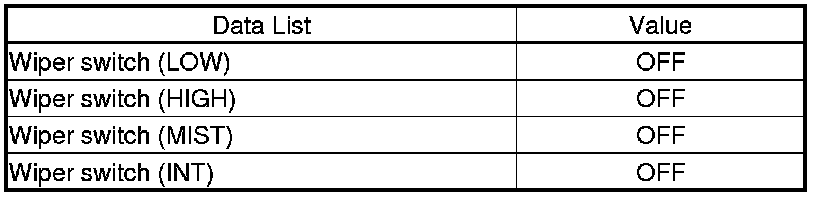
7. Check each wiper switch position value with the DATA LIST menu.

When the wiper switch is turned OFF

Factory service manual diagram


Are all data list values correct?

YES -

Go to step 8.

NO -

Go to step 11.

8. Turn the ignition switch to LOCK (0), or press the engine start/stop button to select the OFF mode.

9. Disconnect driver's under-dash fuse/relay box connector R (24P).

10. Check for continuity between driver's under-dash fuse/relay box connector R (24P) terminals as shown:

Factory service manual diagram


Is there continuity?

YES -

Repair short between the wires.

NO -

Faulty driver's MICU; replace the driver's under-dash fuse/relay box Drivers Under-Dash Fuse/Relay Box (Drivers MICU) Removal and Installation.
11. Turn the ignition switch to LOCK (0), or press the engine start/stop button to select the OFF mode.

12. Disconnect the 8P connector from the wiper switch.

13. Turn the ignition switch to ON (II), or press the engine start/stop button to select the ON mode.

14. Check each wiper switch position value with the DATA LIST menu.

Factory service manual diagram


Are all data list values correct?

YES -

Replace the wiper/washer switch Service and Repair.

NO -

Go to step 15.

15. Turn the ignition switch to LOCK (0), or press the engine start/stop button to select the OFF mode.

16. Disconnect driver's under-dash fuse/relay box connector R (24P).

17. Check for continuity between body ground and driver's under-dash fuse/relay box connector R (24P) terminals No. 15,No. 16, and No. 17 individually.

Factory service manual diagram


Is there continuity?

YES -

Repair a short to ground in the wire(s).

NO -

Go to step 18.

18. Check for continuity between driver's under-dash fuse/relay box connector R (24P) terminal No. 4 and terminals No. 15,No. 16, and No. 17 respectively.

Factory service manual diagram


Is there continuity?

YES -

Repair a short between the wires.

NO -

Faulty driver's MICU; replace the driver's under-dash fuse/relay box Drivers Under-Dash Fuse/Relay Box (Drivers MICU) Removal and Installation.
Supporting Diagrams & Locations

Reference material from the factory manual for this diagnostic procedure.

Diagram

A/C Leak Detection (B07-025)

Location

Accessory Power Sockets

Location

Active Damper System

Location

ACURALINK

Location

Adaptive Cruise Control (Acc)

Fuse/Relay

B18-020: Warranty Extension: Customer Support Program For Driver's Airbag Inflator For 2013-14 ILX Hybrid And Other Listed Years And Models (Expires February 28, 2026) (B18-020)

Fuse/Relay

2012 ZDX: TQI And New Model Service Information (11-019)

Fuse/Relay

2012 ZDX: TQI And New Model Service Information (11-019)

Fuse/Relay

2012 ZDX: TQI And New Model Service Information (11-019)

Related Procedures

Procedure

A/C Refrigerant (Compressor) Oil Guide (BJA34004)

Procedure

A/C Refrigerant And Oil Type Guide (BJA1330)

Procedure

A/C Refrigerant Type Guide (BJA11220)

Procedure

A/C Refrigerant Types Guide (BJA09917 VERSION 2)

Procedure

Drive Belt Squeaks (10-035)

Procedure

Always Enter Campaign Number On Proof Of Correction Certificate (B13010B)