Advanced Diagnostics
Advanced Diagnostics - DTC P0116: Engine Coolant Temperature (ECT) Sensor 1 Range/Performance Problem
General Description
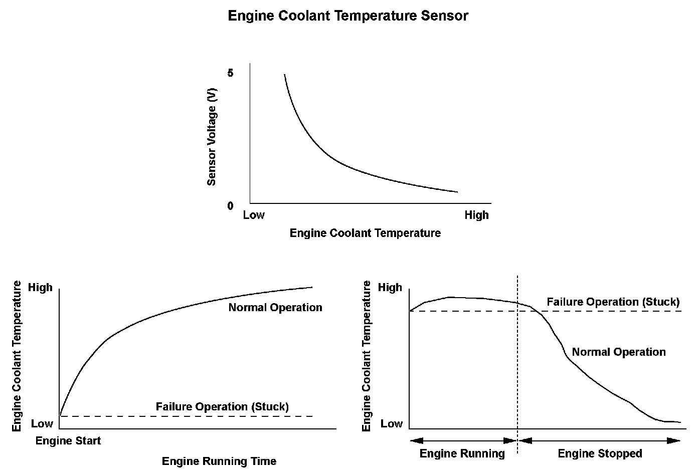
The engine control module (ECM)/powertrain control module (PCM) supplies voltage to the engine coolant temperature signal circuit (about 5 V) through a pull-up resistor. As the engine coolant cools, the engine coolant temperature (ECT) sensor 1 resistance increases, and the ECM/PCM detects a high signal voltage. As the engine coolant warms, the ECT sensor 1 resistance decreases, and the ECM/PCM detects a low signal voltage. If the ECT sensor 1 output voltage does not reach a set temperature after starting the engine and driving a set time, or when the difference between the ECT sensor 1 output voltage while driving and the output voltage of ECT sensor 1 after the engine has been stopped a certain length of time does not change a certain amount, the ECM/PCM detects a malfunction and stores a DTC.
Monitor Execution, Sequence, Duration, DTC Type, OBD Status

Enable Conditions
Malfunction Threshold
Malfunction determination 1:
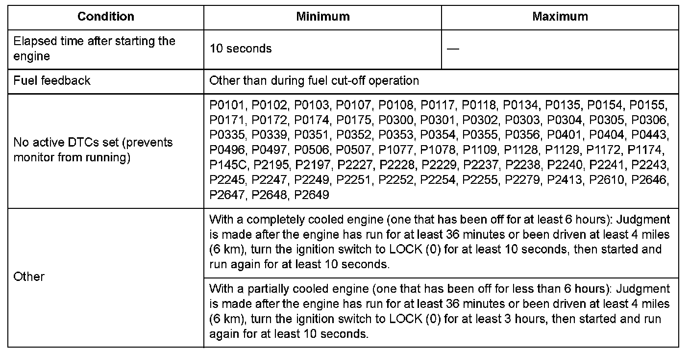
With a completely cooled engine (one that has been off for at least 6 hours):
When the change in coolant temperature after 1 hour or more of running time or 6 miles (10 km) or more of driving distance is 18 °F (10 °C) or less, a malfunction is detected.
Malfunction determination 2:
With a partially cooled engine (one that has been off for less than 6 hours):
When the difference between the coolant temperature after 1 hour or more of running time or 6 miles (10 km) or more of driving distance and the coolant temperature after the engine has been off for 4 hours and then ran for 10 seconds is 18 °F (10 °C) or less, a malfunction is detected.
Driving Pattern
- With a completely cooled engine (one that has been off for at least 6 hours).
1. Start the engine, and let it idle for at least 1 hour or drive for at least 6 miles (10 km).
2. Turn the ignition switch to LOCK (0) for 10 seconds, then restart the engine and let it idle for at least 10 seconds.
- With a partially cooled engine (one that has been off for less than 6 hours).
1. Start the engine, and let it idle for at least 1 hour or drive for at least 6 miles (10 km).
2. Turn the ignition switch to LOCK (0) for 4 hours then restart the engine and let it idle for at least 10 seconds.
Diagnosis Details
Conditions for setting the DTC
When a malfunction is detected during the first drive cycle, a Pending DTC is stored in the ECM/PCM memory. If the malfunction returns in the next (second) drive cycle, the MIL comes on and a Confirmed DTC and the freeze data are stored.
Conditions for clearing the DTC
The MIL is cleared if the malfunction does not return in three consecutive trips in which the diagnostic runs. The MIL, the Pending DTC, the Confirmed DTC, and the freeze data can be cleared with the scan tool Clear command or by disconnecting the battery.
General Description
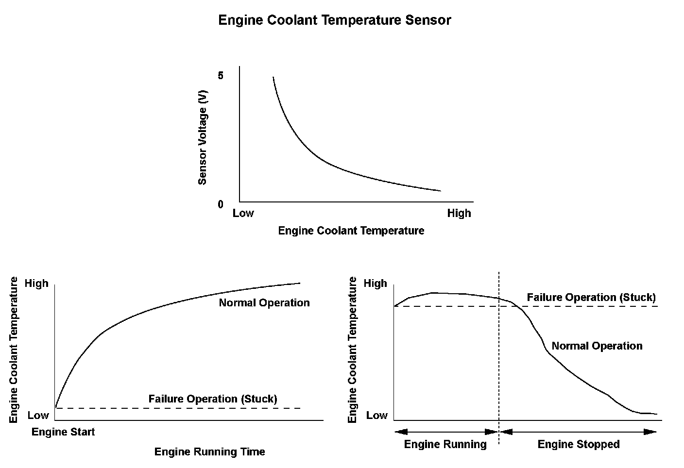
The engine control module (ECM)/powertrain control module (PCM) supplies voltage to the engine coolant temperature signal circuit (about 5 V) through a pull-up resistor. As the engine coolant cools, the engine coolant temperature (ECT) sensor 1 resistance increases, and the ECM/PCM detects a high signal voltage. As the engine coolant warms, the ECT sensor 1 resistance decreases, and the ECM/PCM detects a low signal voltage. If the ECT sensor 1 output voltage does not reach a set temperature after starting the engine and driving a set time, or when the difference between the ECT sensor 1 output voltage while driving and the output voltage of ECT sensor 1 after the engine has been stopped a certain length of time does not change a certain amount, the ECM/PCM detects a malfunction and stores a DTC.
Monitor Execution, Sequence, Duration, DTC Type, OBD Status
Enable Conditions
Malfunction Threshold
Malfunction determination 1:
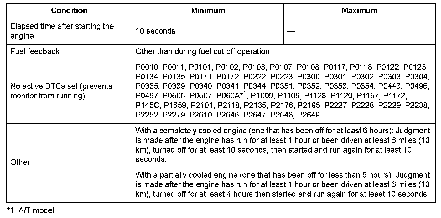
With a completely cooled engine (one that has been off for at least 6 hours):
When the change in coolant temperature after 1 hour or more of running time or 6 miles (10 km) or more of driving distance is 18 °F (10 °C) or less, a malfunction is detected.
Malfunction determination 2:
With a partially cooled engine (one that has been off for less than 6 hours):
When the difference between the coolant temperature after 1 hour or more of running time or 6 miles (10 km) or more of driving distance and the coolant temperature after the engine has been off for 4 hours and then ran for 10 seconds is 18 °F (10 °C) or less, a malfunction is detected.
Driving Pattern
- With a completely cooled engine (one that has been off for at least 6 hours).
1. Start the engine, and let it idle for at least 1 hour or drive for at least 6 miles (10 km).
2. Turn the ignition switch to LOCK (0) for 10 seconds, then restart the engine and let it idle for at least 10 seconds.
- With a partially cooled engine (one that has been off for less than 6 hours).
1. Start the engine, and let it idle for at least 1 hour or drive for at least 6 miles (10 km).
2. Turn the ignition switch to LOCK (0) for 4 hours then restart the engine and let it idle for at least 10 seconds.
Diagnosis Details
Conditions for setting the DTC
When a malfunction is detected during the first drive cycle, a Pending DTC is stored in the ECM/PCM memory. If the malfunction returns in the next (second) drive cycle, the MIL comes on and a Confirmed DTC and the freeze data are stored.
Conditions for clearing the DTC
The MIL is cleared if the malfunction does not return in three consecutive trips in which the diagnostic runs. The MIL, the Pending DTC, the Confirmed DTC, and the freeze data can be cleared with the scan tool Clear command or by disconnecting the battery.