Advanced Diagnostics
Advanced Diagnostics - DTC P0108: Manifold Absolute Pressure (MAP) Sensor Circuit High Voltage
General Description
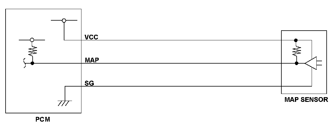
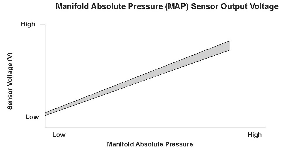
The manifold absolute pressure (MAP) sensor senses manifold absolute pressure (vacuum) and converts it into electrical signals. The MAP sensor outputs low signal voltage at high vacuum (throttle valve closed) and high signal voltage at low vacuum (throttle valve wide open). If the signal voltage from the MAP sensor is a set value, the engine control module (ECM)/ powertrain control module (PCM) detects a malfunction and stores a DTC.
Monitor Execution, Sequence, Duration, DTC Type, OBD Status

Enable Conditions

Malfunction Threshold
The MAP sensor output voltage is 4.49 V or more for at least 2 seconds.
Diagnosis Details
Conditions for setting the DTC
When a malfunction is detected, the MIL comes on and a Pending DTC, a Confirmed DTC, and the freeze data are stored in the ECM/PCM memory.
Conditions for clearing the DTC
The MIL is cleared if the malfunction does not return in three consecutive trips in which the diagnostic runs. The MIL, the Pending DTC, the Confirmed DTC, and the freeze data can be cleared with the scan tool Clear command or by disconnecting the battery.
General Description
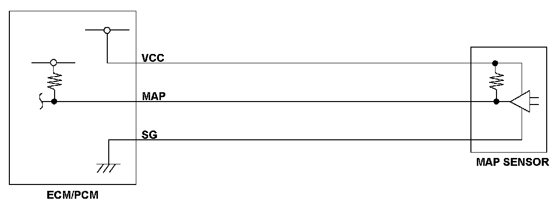
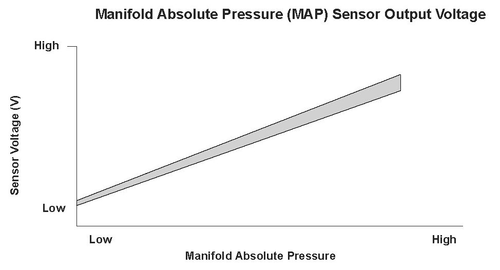
The manifold absolute pressure (MAP) sensor senses manifold absolute pressure (vacuum) and converts it into electrical signals. The MAP sensor outputs low signal voltage at high vacuum (throttle valve closed) and high signal voltage at low vacuum (throttle valve wide open). If the signal voltage from the MAP sensor is a set value, the engine control module (ECM)/ powertrain control module (PCM) detects a malfunction and stores a DTC.
Monitor Execution, Sequence, Duration, DTC Type, OBD Status
Enable Conditions
Malfunction Threshold
The MAP sensor output voltage is 4.49 V or more for at least 2 seconds.
Diagnosis Details
Conditions for setting the DTC
When a malfunction is detected, the MIL comes on and a Pending DTC, a Confirmed DTC, and the freeze data are stored in the ECM/PCM memory.
Conditions for clearing the DTC
The MIL is cleared if the malfunction does not return in three consecutive trips in which the diagnostic runs. The MIL, the Pending DTC, the Confirmed DTC, and the freeze data can be cleared with the scan tool Clear command or by disconnecting the battery.