B1276

Factory Manual References

Factory service manual diagnostic procedure for 2010 acura tl

A L L Diagnostic Trouble Codes ( DTC )

B1275


DTC Troubleshooting: B1275, B1276, B1277, B1278

DTC B1275:

Headlight OFF Position Circuit Malfunction

DTC B1276:

Combination Light Switch Parking (PARKING LIGHT) Position Circuit Malfunction

DTC B1277:

Headlight AUTO Position Circuit Malfunction

DTC B1278:

Headlight ON Position Circuit Malfunction

NOTE: If you are troubleshooting multiple DTCs, be sure to follow the instructions in B-CAN System Diagnosis Test Mode A Troubleshooting - B-CAN System Diagnosis Test Mode A.

1. Clear the DTCs with the HDS.

2. Turn the ignition switch to LOCK (0) and then back to ON (II), or press the engine start/stop button to select the OFF mode and then ON mode.

3. Turn the combination light switch to the PARKING (SMALL), AUTO, and ON (low beam) positions for 6 seconds in each position, and then to the OFF position.

4. Check for DTCs with the HDS.

Are DTCs B1275, B1276, B1277, and/or B1278 indicated?

YES -

Go to step 5.

NO -

Intermittent failure, the system is OK at this time. Check for loose or poor connections.�

5. Select LIGHTING from the BODY ELECTRICAL system select menu, and enter DATA LIST.

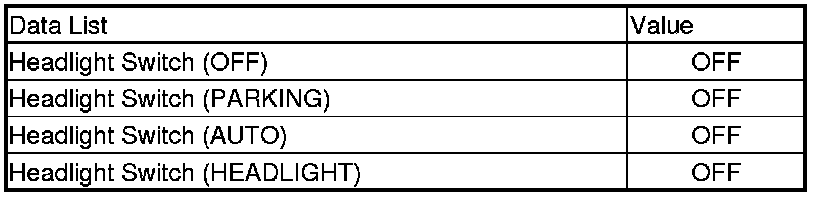
6. Check each combination light switch position value with the DATA LIST menu.

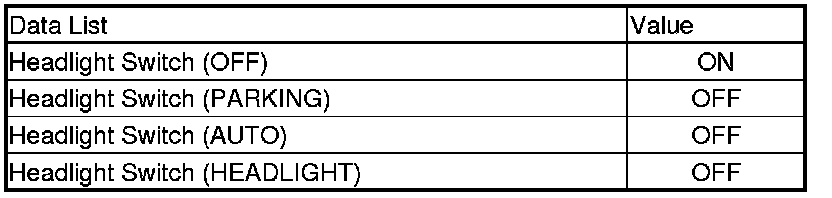
When the combination light switch is turned OFF

Factory service manual diagram


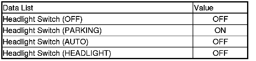
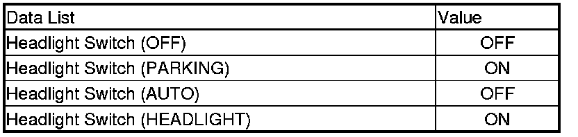
When the combination light switch is turned to PARKING LIGHT

Factory service manual diagram


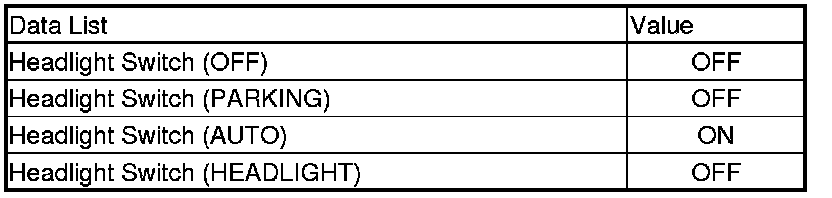
When the combination light switch is turned to AUTO

Factory service manual diagram


When the combination light switch is turned ON (HEADLIGHT)

Factory service manual diagram


Are all data list values correct?

YES -

Faulty driver's MICU; replace the driver's under-dash fuse/relay box Drivers Under-Dash Fuse/Relay Box (Drivers MICU) Removal and Installation.�

NO -

Go to step 7.

7. Turn the ignition switch to LOCK (0), or press the engine start/stop button to select the OFF mode.

8. Disconnect the combination light switch 12P connector.

9. Turn the ignition switch to ON (II), or press the engine start/stop button to select the ON mode.

10. Select LIGHTING from the BODY ELECTRICAL system select menu, and enter DATA LIST.

11. Check each combination light switch position value with the DATA LIST menu.

Factory service manual diagram


Are all data list values indicated OFF?

YES -

Go to step 15.

NO -

Go to step 12.

12. Turn the ignition switch to LOCK (0), or press the engine start/stop button to select the OFF mode.

13. Disconnect driver's under-dash fuse/relay box connector R (24P).

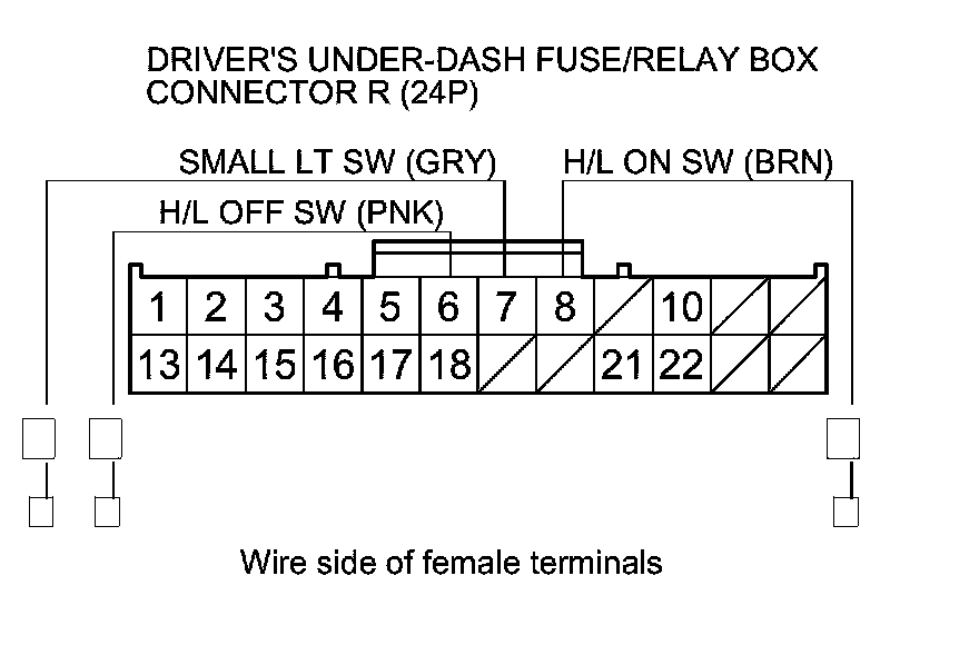
14. Check for continuity between body ground and driver's under-dash fuse/relay box connector R (24P) terminals No. 6,No. 7, and No. 8 individually.

Factory service manual diagram


Is there continuity?

YES -

Repair a short to ground in the wire.�

NO -

Faulty driver's MICU; replace the driver's under-dash fuse/relay box Drivers Under-Dash Fuse/Relay Box (Drivers MICU) Removal and Installation.�

15. Turn the ignition switch to LOCK (0), or press the engine start/stop button to select the OFF mode.

16. Do the combination light switch test Service and Repair.

Is the combination light switch OK?

YES -

Go to step 17.

NO -

Replace the combination light switch.�

17. Disconnect driver's under-dash fuse/relay box connector R (24P).

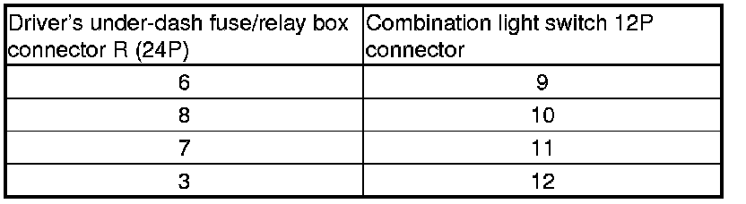
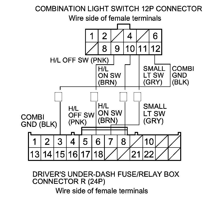
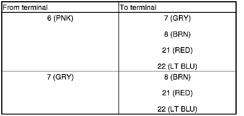
18. Check for continuity between driver's under-dash fuse/relay box connector R (24P) terminals and the combination light switch 12P connector terminals as shown:

Factory service manual diagram


Factory service manual diagram


Is there continuity?

YES -

Go to step 19.

NO -

Repair open in the wire.�

19. Check for continuity between driver's under-dash fuse/relay box connector R (24P) terminals as shown:

Factory service manual diagram


Is there continuity?

YES -

Repair a short between the wires.�

NO -

Faulty driver's MICU; replace the driver's under-dash fuse/relay box Drivers Under-Dash Fuse/Relay Box (Drivers MICU) Removal and Installation.�
B1276


DTC Troubleshooting: B1275, B1276, B1277, B1278

DTC B1275:

Headlight OFF Position Circuit Malfunction

DTC B1276:

Combination Light Switch Parking (PARKING LIGHT) Position Circuit Malfunction

DTC B1277:

Headlight AUTO Position Circuit Malfunction

DTC B1278:

Headlight ON Position Circuit Malfunction

NOTE: If you are troubleshooting multiple DTCs, be sure to follow the instructions in B-CAN System Diagnosis Test Mode A Troubleshooting - B-CAN System Diagnosis Test Mode A.

1. Clear the DTCs with the HDS.

2. Turn the ignition switch to LOCK (0) and then back to ON (II), or press the engine start/stop button to select the OFF mode and then ON mode.

3. Turn the combination light switch to the PARKING (SMALL), AUTO, and ON (low beam) positions for 6 seconds in each position, and then to the OFF position.

4. Check for DTCs with the HDS.

Are DTCs B1275, B1276, B1277, and/or B1278 indicated?

YES -

Go to step 5.

NO -

Intermittent failure, the system is OK at this time. Check for loose or poor connections.�

5. Select LIGHTING from the BODY ELECTRICAL system select menu, and enter DATA LIST.

6. Check each combination light switch position value with the DATA LIST menu.

When the combination light switch is turned OFF

Factory service manual diagram


When the combination light switch is turned to PARKING LIGHT

Factory service manual diagram


When the combination light switch is turned to AUTO

Factory service manual diagram


When the combination light switch is turned ON (HEADLIGHT)

Factory service manual diagram


Are all data list values correct?

YES -

Faulty driver's MICU; replace the driver's under-dash fuse/relay box Drivers Under-Dash Fuse/Relay Box (Drivers MICU) Removal and Installation.�
NO -

Go to step 7.

7. Turn the ignition switch to LOCK (0), or press the engine start/stop button to select the OFF mode.

8. Disconnect the combination light switch 12P connector.

9. Turn the ignition switch to ON (II), or press the engine start/stop button to select the ON mode.

10. Select LIGHTING from the BODY ELECTRICAL system select menu, and enter DATA LIST.

11. Check each combination light switch position value with the DATA LIST menu.

Factory service manual diagram


Are all data list values indicated OFF?

YES -

Go to step 15.

NO -

Go to step 12.

12. Turn the ignition switch to LOCK (0), or press the engine start/stop button to select the OFF mode.

13. Disconnect driver's under-dash fuse/relay box connector R (24P).

14. Check for continuity between body ground and driver's under-dash fuse/relay box connector R (24P) terminals No. 6,No. 7, and No. 8 individually.

Factory service manual diagram


Is there continuity?

YES -

Repair a short to ground in the wire.�

NO -

Faulty driver's MICU; replace the driver's under-dash fuse/relay box Drivers Under-Dash Fuse/Relay Box (Drivers MICU) Removal and Installation.�
15. Turn the ignition switch to LOCK (0), or press the engine start/stop button to select the OFF mode.

16. Do the combination light switch test Service and Repair.

Is the combination light switch OK?

YES -

Go to step 17.

NO -

Replace the combination light switch.�

17. Disconnect driver's under-dash fuse/relay box connector R (24P).

18. Check for continuity between driver's under-dash fuse/relay box connector R (24P) terminals and the combination light switch 12P connector terminals as shown:

Factory service manual diagram


Factory service manual diagram


Is there continuity?

YES -

Go to step 19.

NO -

Repair open in the wire.�

19. Check for continuity between driver's under-dash fuse/relay box connector R (24P) terminals as shown:

Factory service manual diagram


Is there continuity?

YES -

Repair a short between the wires.�

NO -

Faulty driver's MICU; replace the driver's under-dash fuse/relay box Drivers Under-Dash Fuse/Relay Box (Drivers MICU) Removal and Installation.�
Supporting Diagrams & Locations

Reference material from the factory manual for this diagnostic procedure.

Diagram

A/C Leak Detection (B07-025)

Diagram

A/C Leak Detection (B07-025)

Diagram

A/C Leak Detection (B07-025)

Location

ACURA

Location

AUDI

Location

ACURA Torque Converter Clutch Shudder Snap Shot Evaluation Job Aid (JA4659)

Location

Automatic Transmission In-Warranty Exchange Program (90-009)

Fuse/Relay

B1036

Fuse/Relay

B1077

Fuse/Relay

B10A2

Fuse/Relay

B10CF

Related Procedures

Procedure

A/C Refrigerant (Compressor) Oil Guide (BJA34004)

Procedure

A/C Refrigerant And Oil Type Guide (BJA1330)

Procedure

A/C Refrigerant Type Guide (BJA11220)

Procedure

A/C Refrigerant Types Guide (BJA09917 VERSION 2)

Procedure

Always Enter Campaign Number On Proof Of Correction Certificate (B13010B)

Procedure

ACURA Recommended Materials (B99-015)