B1206

Factory Manual References

Factory service manual diagnostic procedure for 2009 acura rdx

A L L Diagnostic Trouble Codes ( DTC )

B1205


DTC Troubleshooting: B1205, B1206, B1207, Indicator H, Indicator J, or Indicator K

DTC B1205 or DTC indicator H: Climate Control Unit Lost Communication with Gauge Control Module (VSP/NE message)

DTC B1206 or DTC indicator K: Climate Control Unit Lost Communication with Gauge Control Module (ECT message)

DTC B1207 or DTC indicator J: Climate Control Unit Lost Communication with Gauge Control Module (ILLUMI message)

NOTE: If you are troubleshooting multiple DTCs, be sure to follow the instructions in B-CAN system diagnosis test mode A. Troubleshooting - B-CAN System Diagnosis Test Mode A

1. Clear the DTC with the HDS.

2. Turn the ignition switch to LOCK (0), and then to ON (II).

3. Do the self-diagnostic with the HDS Initial Inspection and Diagnostic Overview or climate control unit. Initial Inspection and Diagnostic Overview

4. Check for DTCs.

Are DTC B1205 or H indicated?
YES - Go to step 5.

NO - The system is OK at this time, check for loose wires or poor connections on the gauge control module and climate control unit circuit.


5. Check for DTCs with the HDS.

Are DTC B1008, B1011, B1032, B1205, B1206, B1207, and B1906 also indicated?
YES - Go to step 6.

NO - The climate control unit is faulty. Replace the climate control unit.


6. Select UNIT INFORMATION in the BODY ELECTRICAL menu.

7. Select CONNECTED UNIT in the UNIT INFORMATION menu.

Is gauge control module detected?
YES - Substitute a known-good gauge control module, and recheck. If the symptom/indication goes away, replace the gauge control module. Service and Repair

NO - Go to step 8.


8. Disconnect under-dash fuse/relay box connector Q (16P).

9. Disconnect the gauge control module 36P connector.

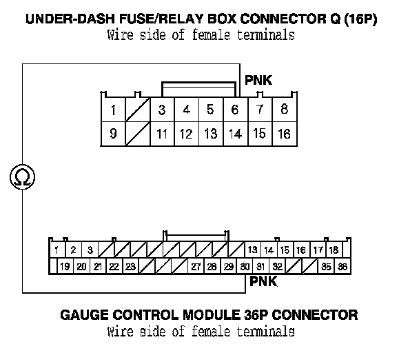
10. Check for continuity between under-dash fuse/relay box connector Q (16P) No. 6 terminal and the gauge control module 36P connector No. 30 terminal.

Is there continuity?
YES - Go to the gauge control module input test. Component Tests and General Diagnostics

NO - Repair open in the wire between the MICU and the gauge control module.


Factory service manual diagram


B1206


DTC Troubleshooting: B1205, B1206, B1207, Indicator H, Indicator J, or Indicator K

DTC B1205 or DTC indicator H: Climate Control Unit Lost Communication with Gauge Control Module (VSP/NE message)

DTC B1206 or DTC indicator K: Climate Control Unit Lost Communication with Gauge Control Module (ECT message)

DTC B1207 or DTC indicator J: Climate Control Unit Lost Communication with Gauge Control Module (ILLUMI message)

NOTE: If you are troubleshooting multiple DTCs, be sure to follow the instructions in B-CAN system diagnosis test mode A. Troubleshooting - B-CAN System Diagnosis Test Mode A

1. Clear the DTC with the HDS.

2. Turn the ignition switch to LOCK (0), and then to ON (II).

3. Do the self-diagnostic with the HDS Initial Inspection and Diagnostic Overview or climate control unit. Initial Inspection and Diagnostic Overview

4. Check for DTCs.

Are DTC B1205 or H indicated?
YES - Go to step 5.

NO - The system is OK at this time, check for loose wires or poor connections on the gauge control module and climate control unit circuit.


5. Check for DTCs with the HDS.

Are DTC B1008, B1011, B1032, B1205, B1206, B1207, and B1906 also indicated?
YES - Go to step 6.

NO - The climate control unit is faulty. Replace the climate control unit.


6. Select UNIT INFORMATION in the BODY ELECTRICAL menu.

7. Select CONNECTED UNIT in the UNIT INFORMATION menu.

Is gauge control module detected?
YES - Substitute a known-good gauge control module, and recheck. If the symptom/indication goes away, replace the gauge control module. Service and Repair

NO - Go to step 8.


8. Disconnect under-dash fuse/relay box connector Q (16P).

9. Disconnect the gauge control module 36P connector.

10. Check for continuity between under-dash fuse/relay box connector Q (16P) No. 6 terminal and the gauge control module 36P connector No. 30 terminal.

Is there continuity?
YES - Go to the gauge control module input test. Component Tests and General Diagnostics

NO - Repair open in the wire between the MICU and the gauge control module.


Factory service manual diagram


Supporting Diagrams & Locations

Reference material from the factory manual for this diagnostic procedure.

Diagram

A/C Leak Detection (B07-025)

Diagram

Connector End Views

Diagram

Air Conditioning

Diagram

Anti-Lock Brakes

Diagram

Anti-Theft

Diagram

Body Control Modules

Location

CHRYSLER Group LLC

Location

CHRYSLER Group LLC

Location

ACURA

Location

AUDI

Fuse/Relay

CHRYSLER Group LLC

Fuse/Relay

AUDI

Fuse/Relay

BMW

Fuse/Relay

CHRYSLER Group LLC

Related Procedures

Procedure

A/C Refrigerant (Compressor) Oil Guide (BJA34004)

Procedure

A/C Refrigerant And Oil Type Guide (BJA1330)

Procedure

A/C Refrigerant Type Guide (BJA11220)

Procedure

A/C Refrigerant Types Guide (BJA09917 VERSION 2)

Procedure

Always Enter Campaign Number On Proof Of Correction Certificate (B13010B)

Procedure

Be Careful Not To Damage That Inner Door Handle Cable End (B10020C)