
B1060

Factory Manual References

Factory service manual diagnostic procedure for 2009 acura rdx

B1805


DTC Troubleshooting: B1805, B1808

DTC B1805: Power Seat Control Unit Lost Communication with Gauge Control Module (VSP/NE Message)

DTC B1808: Power Seat Control Unit Lost Communication with Gauge Control Module (A/T Message)

NOTE: If you are troubleshooting multiple DTCs, be sure to follow the instructions in B-CAN System Diagnosis Test Mode A. Troubleshooting - B-CAN System Diagnosis Test Mode A

1. Clear the DTCs with the HDS.

2. Turn the ignition switch to LOCK (0) and then back to ON (II).

3. Check for DTCs with the HDS.

B1805: Is DTC B1805 indicated? B1808: Is DTC B1808 indicated?
YES - Go to step 4.

NO - Intermittent failure, the system is OK at this time. Check for loose or poor connections.


4. Check for DTCs with the HDS.

B1805: Are DTCs B1060, B1205, B1357, B2010, and B2160 also indicated? B1808: Are DTCs B1008, B1061, B1956, B2011, and/or B2061 also indicated?
YES - Go to step 5.

NO - Replace the power seat control unit.


5. Disconnect power seat control unit connector A (40P) and the gauge control module 36P connector.

6. Check for the continuity between power seat control unit connector A (40P) terminals No. 40 and gauge control module 36P connector terminals No. 30.

Is there continuity?
YES - Replace the gauge control module.

NO - Repair an open in the wire.
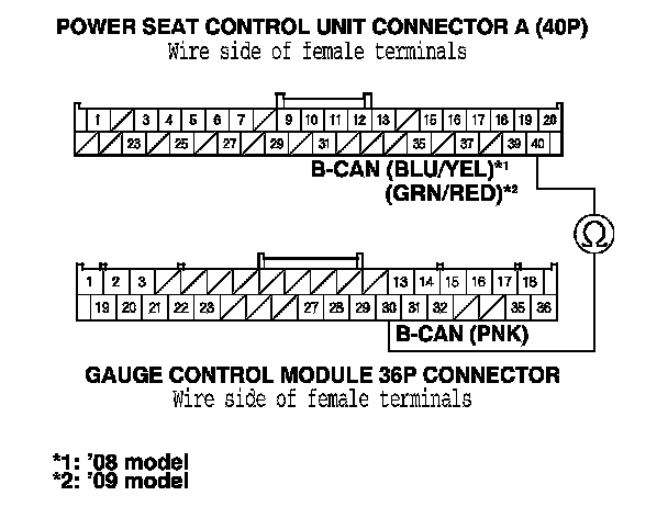

Factory service manual diagram


B1808


DTC Troubleshooting: B1805, B1808

DTC B1805: Power Seat Control Unit Lost Communication with Gauge Control Module (VSP/NE Message)

DTC B1808: Power Seat Control Unit Lost Communication with Gauge Control Module (A/T Message)

NOTE: If you are troubleshooting multiple DTCs, be sure to follow the instructions in B-CAN System Diagnosis Test Mode A. Troubleshooting - B-CAN System Diagnosis Test Mode A

1. Clear the DTCs with the HDS.

2. Turn the ignition switch to LOCK (0) and then back to ON (II).

3. Check for DTCs with the HDS.

B1805: Is DTC B1805 indicated? B1808: Is DTC B1808 indicated?
YES - Go to step 4.

NO - Intermittent failure, the system is OK at this time. Check for loose or poor connections.


4. Check for DTCs with the HDS.

B1805: Are DTCs B1060, B1205, B1357, B2010, and B2160 also indicated? B1808: Are DTCs B1008, B1061, B1956, B2011, and/or B2061 also indicated?
YES - Go to step 5.

NO - Replace the power seat control unit.


5. Disconnect power seat control unit connector A (40P) and the gauge control module 36P connector.

6. Check for the continuity between power seat control unit connector A (40P) terminals No. 40 and gauge control module 36P connector terminals No. 30.

Is there continuity?
YES - Replace the gauge control module.

NO - Repair an open in the wire.


Factory service manual diagram


Supporting Diagrams & Locations

Reference material from the factory manual for this diagnostic procedure.

Diagram

A/C Leak Detection (B07-025)

Diagram

Connector End Views

Diagram

Air Conditioning

Diagram

Anti-Lock Brakes

Diagram

Anti-Theft

Diagram

Body Control Modules

Location

CHRYSLER Group LLC

Location

CHRYSLER Group LLC

Location

ACURA

Location

AUDI

Fuse/Relay

CHRYSLER Group LLC

Fuse/Relay

AUDI

Fuse/Relay

BMW

Fuse/Relay

CHRYSLER Group LLC

Related Procedures

Procedure

A/C Refrigerant (Compressor) Oil Guide (BJA34004)

Procedure

A/C Refrigerant And Oil Type Guide (BJA1330)

Procedure

A/C Refrigerant Type Guide (BJA11220)

Procedure

A/C Refrigerant Types Guide (BJA09917 VERSION 2)

Procedure

Always Enter Campaign Number On Proof Of Correction Certificate (B13010B)

Procedure

Be Careful Not To Damage That Inner Door Handle Cable End (B10020C)