
P1744

Factory Manual References

Factory service manual diagnostic procedure for 2007 audi a4

01J, Continuously Variable Transmission (CVT)


DTC 18152 / P1744 - 01J, Continuously Variable Transmission (CVT)
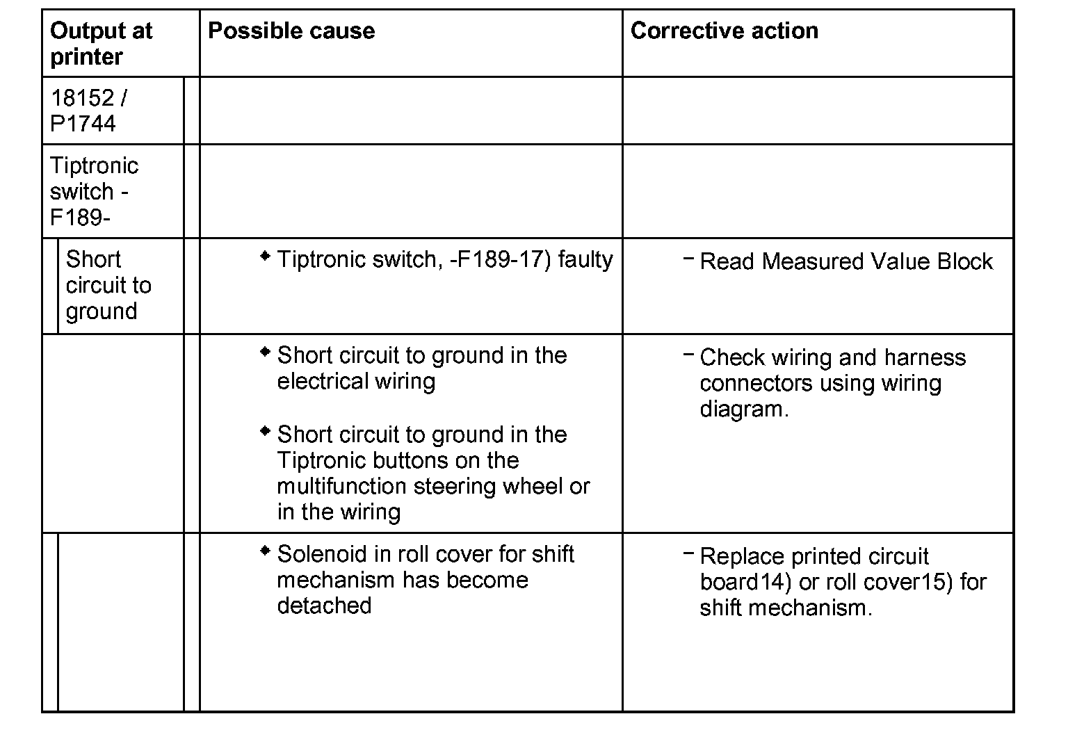
Factory service manual diagram


14) The Tiptronic switch -F189- consists of switches for recognition, upshift and downshift. It is integrated in the shift mechanism printed circuit board, i.e. if the Tiptronic switch -F189- is faulty, the printed-circuit board has to be replaced.
15) The Tiptronic switch -F189- receives its Tiptronic gate recognition or upshift/downshift information through the solenoid on the transverse slide for the roll cover. If the solenoid has become detached, the cover must be replaced.
17) If the transmission is shifted into the Tiptronic gate with the selector lever in D this shift procedure is recognized by the Tiptronic recognition switch -F189- and transmitted to the Transmission Control Module (TCM).

Note on DTC 18152 / P1744:
^ DTC is displayed if Tiptronic recognition was detected, although the selector lever is not in the Tiptronic gate.

01J, Continuously Variable Transmission (CVT)


DTC 18152 / P1744 - 01J, Continuously Variable Transmission (CVT)

Factory service manual diagram


14) The Tiptronic switch -F189- consists of switches for recognition, upshift and downshift. It is integrated in the shift mechanism printed circuit board, i.e. if the Tiptronic switch -F189- is faulty, the printed-circuit board has to be replaced.
15) The Tiptronic switch -F189- receives its Tiptronic gate recognition or upshift/downshift information through the solenoid on the transverse slide for the roll cover. If the solenoid has become detached, the cover must be replaced.
17) If the transmission is shifted into the Tiptronic gate with the selector lever in D this shift procedure is recognized by the Tiptronic recognition switch -F189- and transmitted to the Transmission Control Module (TCM).

Note on DTC 18152 / P1744:
^ DTC is displayed if Tiptronic recognition was detected, although the selector lever is not in the Tiptronic gate.

01J, Continuously Variable Transmission (CVT)


DTC 18152 / P1744 - 01J, Continuously Variable Transmission (CVT)

Factory service manual diagram


14) The Tiptronic switch -F189- consists of switches for recognition, upshift and downshift. It is integrated in the shift mechanism printed circuit board, i.e. if the Tiptronic switch -F189- is faulty, the printed-circuit board has to be replaced.
15) The Tiptronic switch -F189- receives its Tiptronic gate recognition or upshift/downshift information through the solenoid on the transverse slide for the roll cover. If the solenoid has become detached, the cover must be replaced.
17) If the transmission is shifted into the Tiptronic gate with the selector lever in D this shift procedure is recognized by the Tiptronic recognition switch -F189- and transmitted to the Transmission Control Module (TCM).

Note on DTC 18152 / P1744:
^ DTC is displayed if Tiptronic recognition was detected, although the selector lever is not in the Tiptronic gate.

Supporting Diagrams & Locations

Reference material from the factory manual for this diagnostic procedure.

Location

00 Software Version Management (SVM), Operating Instructions (GROUP 00, NO. 21-55)

Location

00 Software Version Management (SVM), Operating Instructions (GROUP 00, NO. 21-55)

Location

00 Software Version Management (SVM), Operating Instructions (GROUP 00, NO. 21-55)

Location

00 Software Version Management (SVM), Operating Instructions (GROUP 00, NO. 21-55)