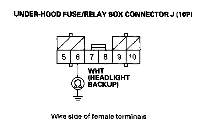
DTC B1075: Headlight Signal ErrorNOTE: If you are troubleshooting multiple DTCs, be sure to follow the instructions in B-CAN System Diagnosis Test mode A.
1.
Clear the DTCs with the HDS.
2.
Turn the headlights switch from the OFF position to the ON position.
3.
Check for DTCs with the HDS.
Is DTC B1075 indicated?
YES - Go to step 4.
NO - Intermittent failure, the headlight circuit is OK at this time. Check for loose or poor connections at under-hood fuse/relay box connector J (10P), and at the combination switch connector.
4.
With the headlight switch OFF, select LIGHTING SYSTEM from the HDS, and enter the DATA LIST.
5.
Check the ON/OFF information of the Headlight Switch (BACK-UP) in the DATA LIST.
Is the information indicator OFF?
YES - Go to step 6.
NO - Go to step 10.
6.
Turn the headlight switch ON.
7.
Check the ON/OFF information of the Headlight Switch (BACK-UP) in the DATA LIST.
Is the information indicator ON?
YES - Faulty relay control module; replace the under-hood fuse/relay box.
NO - Go to step 8.
8.
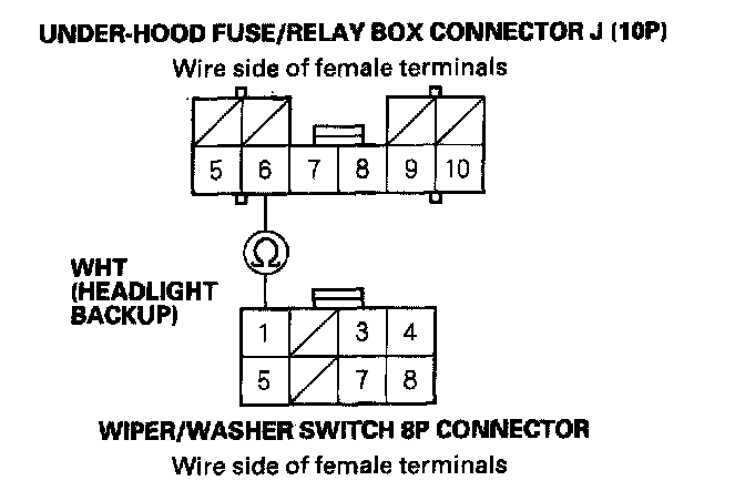
Disconnect the under-hood fuse/relay box connector J (10P) and the wiper/washer switch 8P connector.
9.
Check for continuity between the No. 6 terminal of the under-hood fuse/relay box connector J (10P) and the No. 1 terminal of the wiper/washer switch (combination switch control unit) 8P connector.
Is there continuity?
YES - Faulty combination switch control unit or relay control module; substitute a known-good wiper/washer switch and retest. If the DTC is no longer present, replace the original wiper/washer switch. If the DTC is still present, the relay control module is faulty, replace the under-hood fuse/relay box.
NO - Repair an open in the WHT wire.
10.
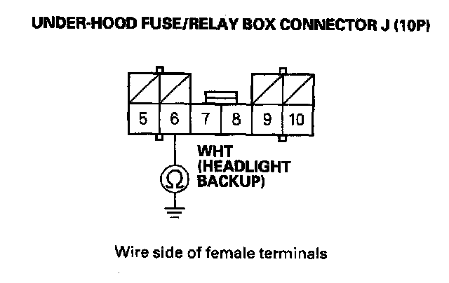
Disconnect the under-hood fuse/relay box connector J (10P).
11.
Check for continuity between the No. 6 terminal of the under-hood fuse/relay box connector J (10P) and body ground.
Is there continuity?
YES - Go to step 12.
NO - Faulty relay control module; replace the under-hood fuse/relay box.
12.
Disconnect the combination light switch 12P connector from the wiper/washer switch.
13.
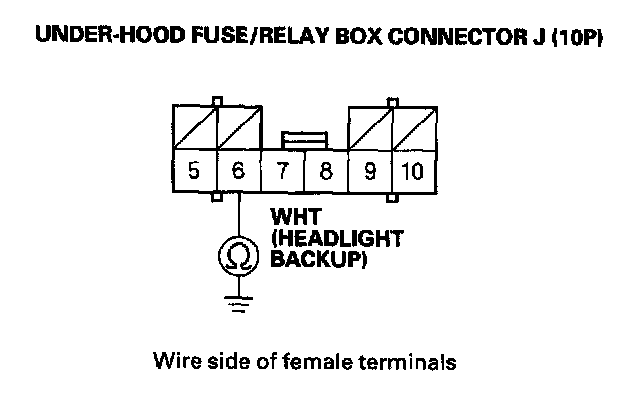
Check for continuity between the No. 6 terminal of the under-hood fuse/relay box connector J (10P) and body ground.
Is there continuity?
YES - Go to step 14.
NO - Faulty combination switch control unit; replace it.
14.
Disconnect the wiper/washer switch 8P connector.
15.
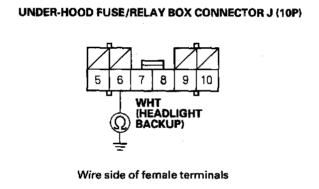
Check for continuity between the No. 6 terminal of the under-hood fuse/relay box connector J (10P) and body ground.
Is there continuity?
YES - Go to step 16.
NO - Faulty combination switch control unit;replace the wiper/washer switch.
16.
Disconnect the driver's under-dash fuse/relay box connector P (30P).
17.
Check for continuity between the No. 6 terminal of the under-hood fuse/relay box connector J (10P) and body ground.
Is there continuity?
YES - Repair a short in the WHT wire.
NO - Faulty combination switch control unit; replace the wiper/washer switch.