
P1762
Factory Manual ReferencesFactory service manual diagnostic procedure for 2005 audi allroad

01V, 5 Speed A/T
DTC 18169 / P1761

Note:
Notes and footnotes for DTC 18169 / P1761 can be found on the next DTC.
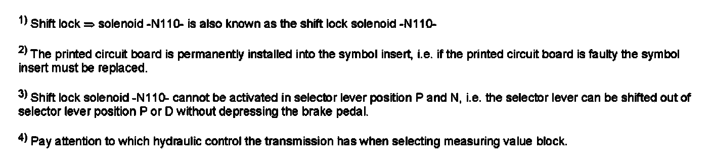
1) Shift lock solenoid -N110- is also known as the shift lock solenoid -N110-
2) The printed circuit board is permanently installed into the symbol insert, i.e. if the printed circuit board is faulty the symbol insert must be replaced.
3) Shift lock solenoid -N110- cannot be switched off, i.e. the selector lever can also not be shifted out of selector lever position P or D by depressing the brake pedal.
4) Pay attention to which hydraulic control the transmission has when selecting measuring value block. For a more detailed description; Refer to "Read measuring value block".
01L, 5 Speed A/T AWD
Supporting Diagrams & Locations
Reference material from the factory manual for this diagnostic procedure.
Diagram
2.7L Turbo
Diagram
4.2L
Diagram
2.7L Turbo
Diagram
4.2L
Diagram
2.7L Turbo
Diagram
4.2L
Location
00 Software Version Management (SVM), Operating Instructions (GROUP 00, NO. 21-55)
Location
57 Vehicle Locking System, Diagnostic Information (GROUP 57, NO. 24-65)
Location
00 Software Version Management (SVM), Operating Instructions (GROUP 00, NO. 21-55)
Location
00 Software Version Management (SVM), Operating Instructions (GROUP 00, NO. 21-55)