
P0703

Factory Manual References

Factory service manual diagnostic procedure for 2005 audi allroad

01L, 5 Speed Automatic AWD


Diagnostic Trouble Code (DTC) tables

Note:
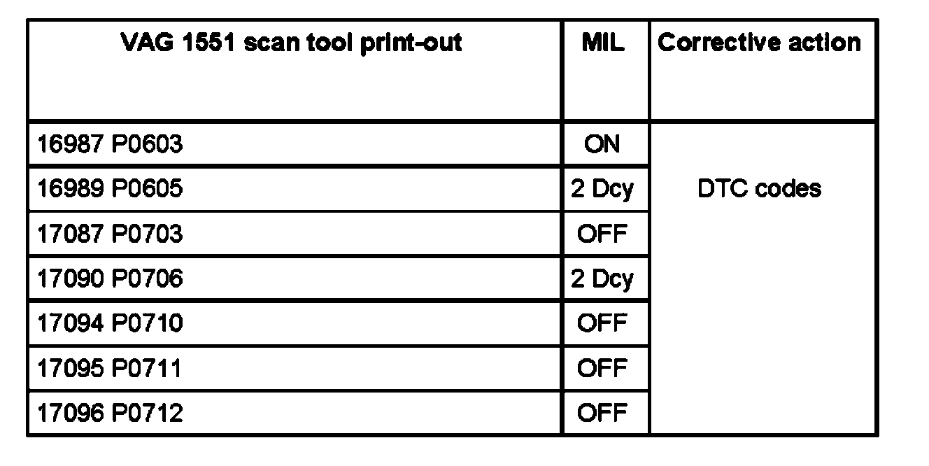
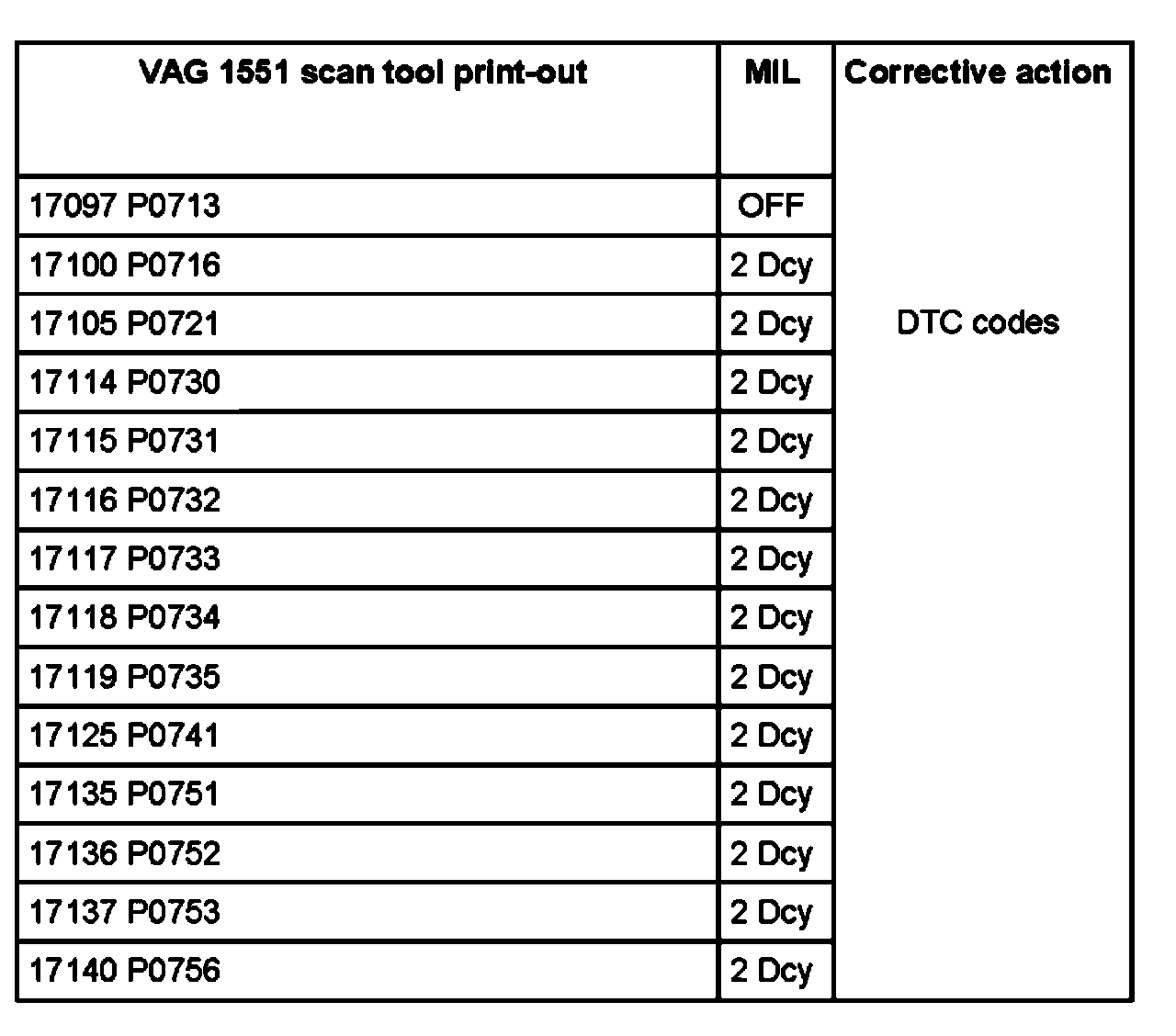
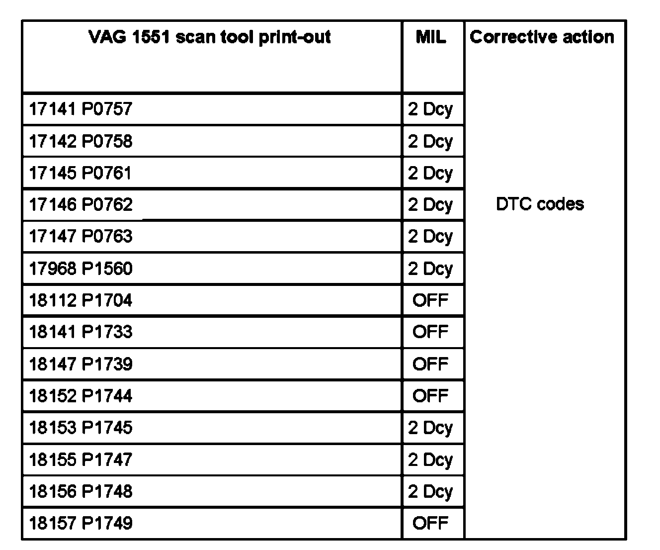
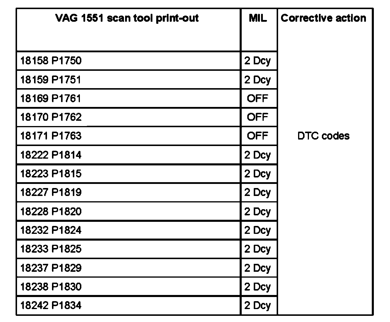
^ The following table contains all possible malfunctions that are recognized by the Transmission Control Module (TCM) -J217- and displayed by the VAG 1551 or VAG 1552 Scan Tools (S7) when the Diagnostic Trouble Code (DTC) memory is checked.
^ If malfunctions occur occasionally or if the DTC memory was not erased after corrections were made, these malfunctions are indicated as "sporadic" for a specified amount of time. For an explanation of malfunctions recognized by the TCM see.
^ The DTC is printed out in the "Rapid data transfer" mode only when the printer of the VAG 1551 Scan Tool is switched on. Example: DTC 17087 P0703 (VAG code and P-code)
^ If components were determined to be malfunctioning when the DTC memory is checked, check the wiring and components for short circuit and open circuit according to latest wiring diagram.

Diagnostic Trouble Code (DTC) tables Part 1:
Factory service manual diagram


Diagnostic Trouble Code (DTC) tables Part 2:
Factory service manual diagram


Diagnostic Trouble Code (DTC) tables Part 3:
Factory service manual diagram


Diagnostic Trouble Code (DTC) tables Part 4:
Factory service manual diagram


Diagnostic Trouble Code (DTC) tables Part 5:
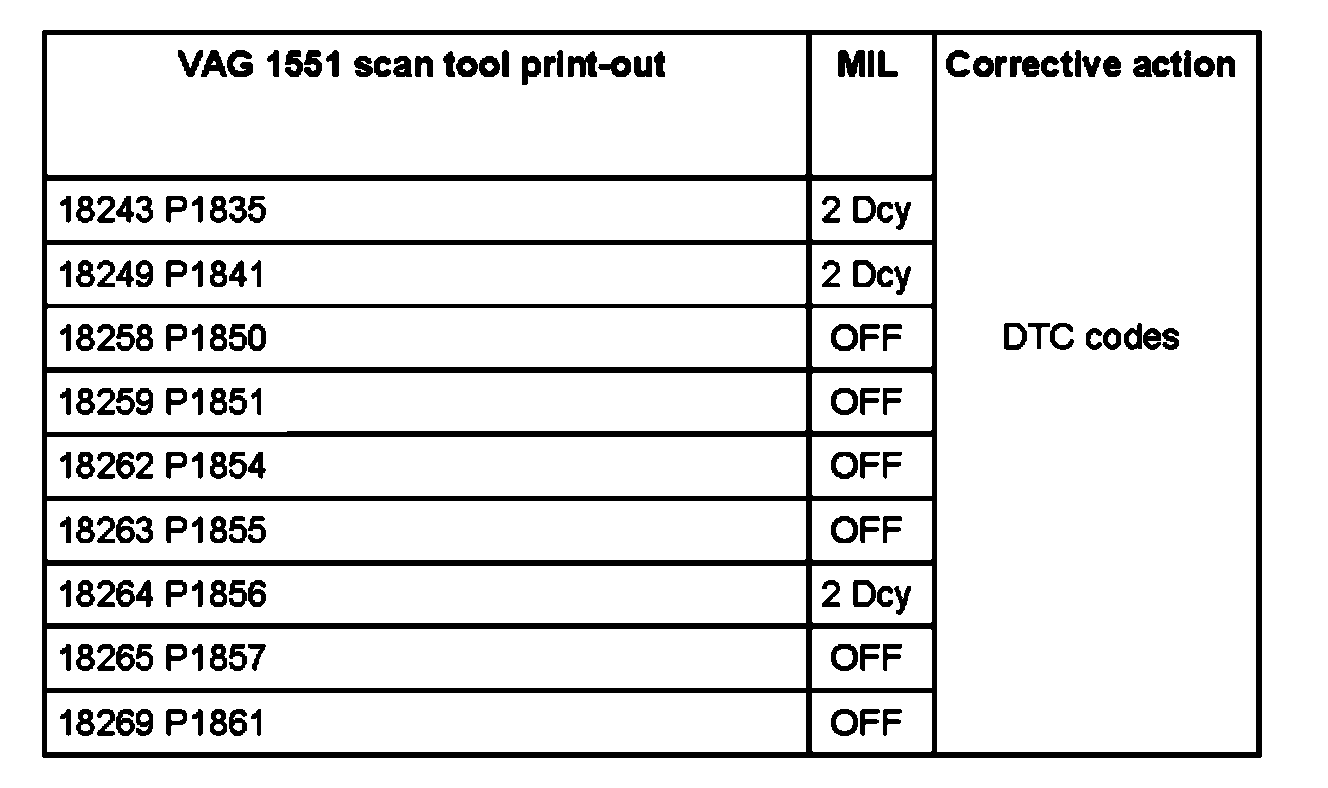
Factory service manual diagram


Note:
^ DCY = Driving cycle, conditions to recognize a DCY.
^ Explanation for emission warning light Multi-function Indicator Lamp (MIL).
^ The "MIL" column in the DTC table indicates the condition for which the MIL will be switched on. If, for example, "2Dcy" is indicated, it means that the MIL will be switched on after 2 driving cycles. If "Off" is indicated, the malfunction has no influence on the MIL. If "On" is indicated, the MIL will be switched on immediately when the malfunction occurs.
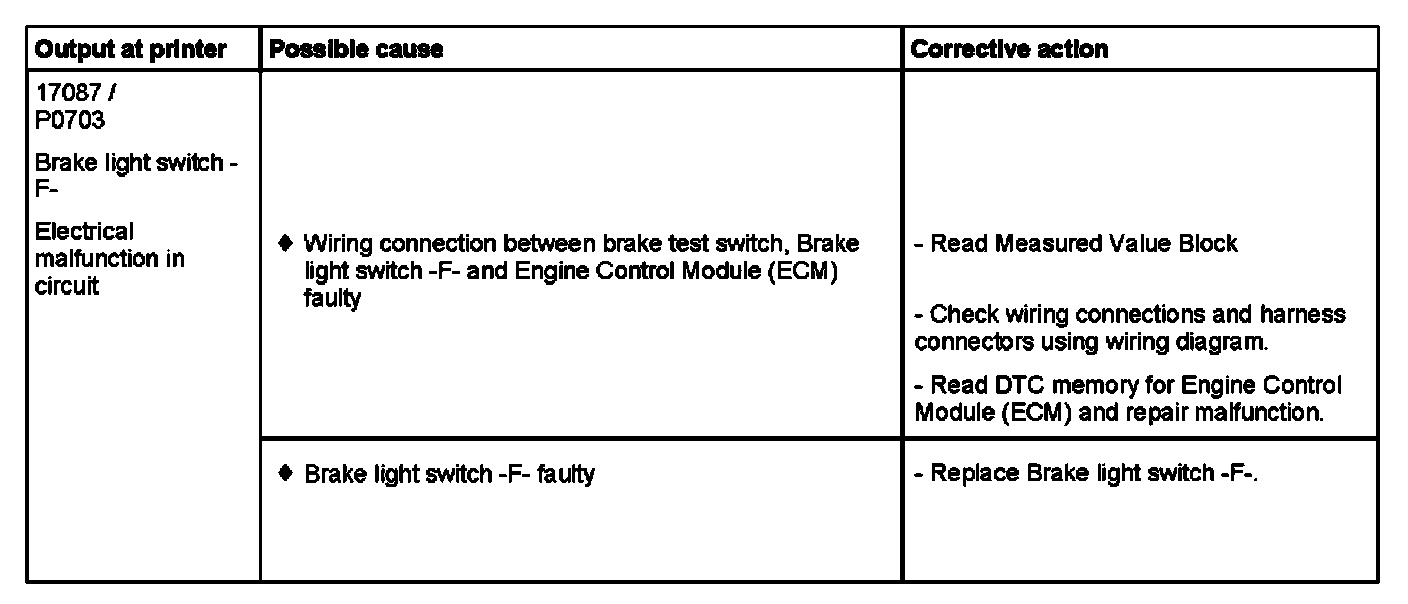
01J, Constantly Variable Transmission (CVT)


DTC 17087 / P0703

Factory service manual diagram


Note on DTC 17087 / P0703:
^ Conditions for DTC recognition: The signals from the brake light switch and the brake test switch are transmitted over the CAN bus circuit to the Transmission Control Module (TCM) and evaluated there. After 10 consecutive occurrences of an implausibility between the brake light switch and the brake test switch (one switch actuated, the other not) this DTC is saved in the Transmission Control Module (TCM).

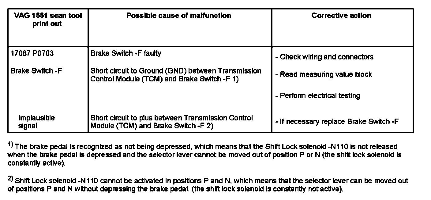
01L, 5 Speed A/T AWD


DTC 17087 / P0703

Factory service manual diagram


Note for DTC 17087 / P0703:
^ The malfunction is pre-set when the ignition is switched on. The pre-set DTC is erased after the brake pedal has been activated once if the Brake Switch -F is OK
^ Step on the brake pedal before checking the DTC memory to erase the pre-set DTC.

Supporting Diagrams & Locations

Reference material from the factory manual for this diagnostic procedure.

Diagram

2.7L Turbo

Diagram

4.2L

Diagram

2.7L Turbo

Diagram

4.2L

Diagram

2.7L Turbo

Diagram

4.2L

Location

00 Software Version Management (SVM), Operating Instructions (GROUP 00, NO. 21-55)

Location

57 Vehicle Locking System, Diagnostic Information (GROUP 57, NO. 24-65)

Location

00 Software Version Management (SVM), Operating Instructions (GROUP 00, NO. 21-55)

Location

00 Software Version Management (SVM), Operating Instructions (GROUP 00, NO. 21-55)