
P0752

Factory Manual References

Factory service manual diagnostic procedure for 2004 audi allroad

01V, 5 Speed A/T


DTC 17135 / P0751
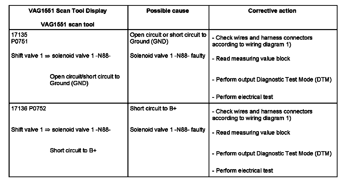
Factory service manual diagram


Factory service manual diagram


Note:
Notes and footnotes of DTCs 17135 / P0751 and 17136 / P0752 can be found on the next DTC.

1) First check harness connectors for contact corrosion and water ingress, replace if necessary. If there are malfunctions indicated for solenoid valves, pay particular attention to the 16-pin harness connector at transmission between valve body and cable harness.

2) Pay attention to which hydraulic control the transmission has when selecting measuring value block. For a more detailed description; Refer to "Read measuring value block".

Note: For malfunction recognition of DTCs 17135 / P0751 and 17136 / P0752

^ Short circuit to B+ is already checked with ignition switched on. During operation, all malfunction types are recognized.
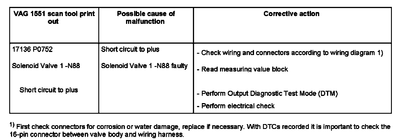
01L, 5 Speed A/T AWD


DTC 17136 / P0752

Factory service manual diagram


Note for DTC 17136 / P0752
^ Short circuit to plus is already checked when the ignition is switched on. During driving, all fault possibilities are going to be recognized.

01V, 5 Speed A/T


DTC 17136 / P0752

Factory service manual diagram


Note:
Notes and footnotes of DTCs 17135 / P0751 and 17136 / P0752 can be found on the next DTC.

1) First check harness connectors for contact corrosion and water ingress, replace if necessary. If there are malfunctions indicated for solenoid valves, pay particular attention to the 16-pin harness connector at transmission between valve body and cable harness.

2) Pay attention to which hydraulic control the transmission has when selecting measuring value block. For a more detailed description; Refer to "Read measuring value block".

Note: For malfunction recognition of DTCs 17135 / P0751 and 17136 / P0752

^ Short circuit to B+ is already checked with ignition switched on. During operation, all malfunction types are recognized.

Supporting Diagrams & Locations

Reference material from the factory manual for this diagnostic procedure.

Diagram

2.7L Turbo

Diagram

4.2L

Diagram

2.7L Turbo

Diagram

4.2L

Diagram

2.7L Turbo

Diagram

4.2L

Location

ACURA

Location

00 Software Version Management (SVM), Operating Instructions (GROUP 00, NO. 21-55)

Location

Airbag Or Pyrotechnic Safety Belt Deployment, Inquiries (GROUP 69, NO. 97-03)

Location

00 Software Version Management (SVM), Operating Instructions (GROUP 00, NO. 21-55)

Related Procedures

Procedure

Adjusting door component carrier

Procedure

Adjusting door component carrier

Procedure

Adjusting door component carrier
