P0730

Factory Manual References

Factory service manual diagnostic procedure for 2004 audi allroad

01J, Constantly Variable Transmission (CVT)


P0730

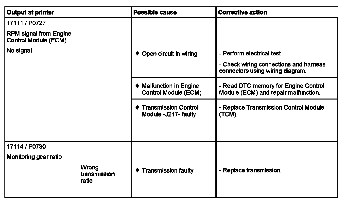
Factory service manual diagram


Note on DTC 17111 / P0727:
^ In the event of an open circuit in the RPM lead, the substitute engine RPM signal is transmitted by the Engine Control Module (ECM) over the CAN bus circuit to the Transmission Control Module (TCM).

01L, 5 Speed A/T AWD


DTC 17114 / P0730

Factory service manual diagram


Note for DTC 17114 / P0730:
^ The monitoring of the transmission range by the Transmission Control Module (TCM) controls the transmission ratios by comparing transmission input and output RPM for the applicable engaged transmission range. This TDC is shown when an improper transmission ratio is detected (implausibility).
^ Men checking the full braking speed RPM, the transmission input RPM (when the car is not moving and a transmission range engaged) must be almost 0 at the torque converter. If this is not the case, this DTC is still shown since there could be a fault with the clutch (Read measuring value block; display group number 001).

01V, 5 Speed A/T


DTC 17114 / P0730

Factory service manual diagram


Note:
The footnotes and notes for DTC 17114 / P0730 can be found on the next DTC.

Note:
For malfunction recognition of DTC 17114 / P0730:

^ Gear monitoring of the Transmission Control Module (TCM) checks the translation ratio by comparing transmission input RPM and transmission output RPM based on the currently selected gear. This malfunction is indicated when an unrecognized, unauthorized gear ratio occurs (implausibility)

^ When checking the standstill RPM, the transmission input RPM in converter at standstill with gear selected must be close to zero. If this is not the case, this malfunction is also displayed since clutch may be damaged (Read measuring value block; Display group number 001).

Supporting Diagrams & Locations

Reference material from the factory manual for this diagnostic procedure.

Diagram

2.7L Turbo

Diagram

4.2L

Diagram

2.7L Turbo

Diagram

4.2L

Diagram

2.7L Turbo

Diagram

4.2L

Location

ACURA

Location

00 Software Version Management (SVM), Operating Instructions (GROUP 00, NO. 21-55)

Location

Airbag Or Pyrotechnic Safety Belt Deployment, Inquiries (GROUP 69, NO. 97-03)

Location

00 Software Version Management (SVM), Operating Instructions (GROUP 00, NO. 21-55)

Related Procedures

Procedure

Adjusting door component carrier

Procedure

Adjusting door component carrier

Procedure

Adjusting door component carrier