A L L Diagnostic Trouble Codes ( DTC )
 Testing and Inspection
- Diagnostic Trouble Code Descriptions
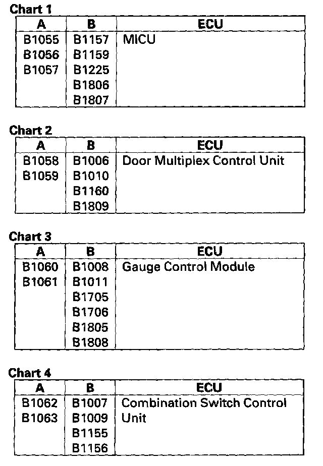
- B Code Charts
- B1000
- B1001
- B1002
- B1005
- B1006
- B1007
- B1008
- B1010
- B1011
- B1026
- B1050
- B1055
- B1056
- B1057
- B1058
- B1059
- B1060
- B1061
- B1062
- B1063
- B1075
- B1076
- B1077
- B1080
- B1100
- B1102
- B1120
- B1125
- B1126
- B1127
- B1128
- B1129
- B1130
- B1131
- B1140
- B1141
- B1142
- B1143
- B1144
- B1145
- B1146
- B1150
- B1152
- B1155
- B1156
- B1157
- B1158
- B1159
- B1160
- B1168
- B1169
- B1175
- B1177
- B1178
- B1202
- B1225
- B1226
- B1227
- B1228
- B1229
- B1230
- B1231
- B1232
- B1233
- B1234
- B1235
- B1236
- B1237
- B1238
- B1239
- B1240
- B1241
- B1242
- B1243
- B1250
- B1255
- B1275
- B1276
- B1278
- B1279
- B1280
- B1281
- B1282
- B1283
- B1284
- B1700
- B1701
- B1702
- B1705
- B1706
- B1725
- B1726
- B1750
- B1751
- B1775
- B1776
- B1779
- B1780
- B1792
- B1800
- B1802
- B1805
- B1806
- B1807
- B1808
- B1809
- B1825
- B1826
- B1827
- B1828
- B1829
- B1830
- B1831
- B1832
- B1833
- B1834
- B1837
- B1843
- P Code Charts
- All Other P Codes
- P2A00
- P2A03
- P0107
- P0108
- P0112
- P0113
- P0116
- P0117
- P0118
- P0122
- P0123
- P0125
- P0128
- P0133
- P0134
- P0135
- P0137
- P0138
- P0139
- P0141
- P0153
- P0154
- P0155
- P0157
- P0158
- P0159
- P0161
- P0171
- P0172
- P0174
- P0175
- P0222
- P0223
- P0300
- P0301
- P0302
- P0303
- P0304
- P0305
- P0306
- P0325
- P0335
- P0339
- P0340
- P0344
- P0385
- P0389
- P0401
- P0404
- P0406
- P0420
- P0430
- P0442
- P0443
- P0451
- P0452
- P0453
- P0456
- P0457
- P0496
- P0497
- P0498
- P0499
- P0506
- P0507
- P0563
- P0603
- P0630
- P0685
- P0700
- P0705
- P0706
- P0711
- P0712
- P0713
- P0715
- P0716
- P0717
- P0718
- P0720
- P0721
- P0722
- P0723
- P0731
- P0732
- P0733
- P0734
- P0735
- P0741
- P0746
- P0747
- P0751
- P0752
- P0756
- P0757
- P0761
- P0762
- P0776
- P0777
- P0780
- P0815
- P0816
- P0847
- P0848
- P0872
- P0873
- P0957
- P0958
- P0962
- P0963
- P0966
- P0967
- P0970
- P0971
- P0973
- P0974
- P0976
- P0977
- P0979
- P0980
- P1077
- P1078
- P1128
- P1129
- P1297
- P1298
- P1454
- P1683
- P1684
- P2101
- P2108
- P2118
- P2122
- P2123
- P2127
- P2128
- P2135
- P2138
- P2176
- P2195
- P2197
- P2227
- P2228
- P2229
- P2237
- P2238
- P2240
- P2241
- P2243
- P2245
- P2247
- P2249
- P2251
- P2252
- P2254
- P2255
- P2279
- P2413
- P2422
- P2552
- P2627
- P2628
- P2630
- P2631
- P2646
- P2647
- P2648
- P2649
- P2769
- P2770
- U Code Charts
- Manufacturer Code Charts
- Air Bag System (SRS)
- DTC A1-1x
- DTC A2-1x
- DTC E4-11
- DTC F1-11
- DTC F2-11
- DTC F3-11
- DTC F4-11
- DTC 11-Ax
- DTC 11-Bx
- DTC 11-1x
- DTC 11-3x
- DTC 11-4x
- DTC 11-6x
- DTC 11-8x
- DTC 11-9x
- DTC 12-Ax
- DTC 12-Bx
- DTC 12-1x
- DTC 12-3x
- DTC 12-4x
- DTC 12-6x
- DTC 12-8x
- DTC 12-9x
- DTC 21-1x
- DTC 21-3x
- DTC 21-8x
- DTC 21-9x
- DTC 22-1X
- DTC 22-3x
- DTC 22-8x
- DTC 22-9x
- DTC 31-1x
- DTC 31-3x
- DTC 31-8x
- DTC 31-9x
- DTC 32-1x
- DTC 32-3x
- DTC 32-8x
- DTC 32-9x
- DTC 33-1x
- DTC 33-3x
- DTC 33-8x
- DTC 33-9x
- DTC 34-1x
- DTC 34-3x
- DTC 34-8x
- DTC 34-9x
- DTC 41-Bx
- DTC 41-1x
- DTC 41-2x
- DTC 41-3x
- DTC 42-Bx
- DTC 42-1x
- DTC 42-2x
- DTC 42-3x
- DTC 43-Bx
- DTC 43-1x
- DTC 43-2x
- DTC 43-3x
- DTC 44-Bx
- DTC 44-1x
- DTC 44-2x
- DTC 44-3x
- DTC 45-Bx
- DTC 45-1x
- DTC 45-2x
- DTC 45-3x
- DTC 46-Bx
- DTC 46-1x
- DTC 46-2x
- DTC 46-3x
- DTC 51-2x
- DTC 51-4x
- DTC 52-Ax
- DTC 52-Bx
- DTC 52-Cx
- DTC 52-Dx
- DTC 52-Ex
- DTC 52-Fx
- DTC 52-8x
- DTC 52-9x
- DTC 53-1x
- DTC 53-2x
- DTC 53-3x
- DTC 53-4x
- DTC 54-1x
- DTC 54-2x
- DTC 54-3x
- DTC 54-4x
- DTC 54-5x
- DTC 54-6x
- DTC 54-7x
- DTC 55-1x
- DTC 55-2x
- DTC 55-3x
- DTC 55-4x
- DTC 61-1x
- DTC 61-2x
- DTC 62-1x
- DTC 62-2x
- DTC 85-4x
- DTC 85-5x
- DTC 85-61
- DTC 85-62
- DTC 85-63
- DTC 85-64
- DTC 85-71
- DTC 85-78
- DTC 85-79
- DTC 85-85
- DTC 85-86
- DTC 85-87
- DTC 86-1x
- DTC 86-2x
- DTC 87-31
- DTC 87-32
- DTC 91-1x
- Antilock Brake System
- DTC 11
- DTC 12
- DTC 13
- DTC 14
- DTC 15
- DTC 16
- DTC 17
- DTC 18
- DTC 21
- DTC 22
- DTC 23
- DTC 24
- DTC 25
- DTC 26
- DTC 27
- DTC 31
- DTC 32
- DTC 33
- DTC 34
- DTC 35
- DTC 36
- DTC 37
- DTC 38
- DTC 41
- DTC 42
- DTC 43
- DTC 44
- DTC 51
- DTC 52
- DTC 53
- DTC 54
- DTC 61
- DTC 62
- DTC 64
- DTC 65
- DTC 66
- DTC 68
- DTC 71
- DTC 81
- DTC 83
- DTC 84
- DTC 86
- DTC 107
- DTC 108
- DTC 112
- DTC 121
- DTC 122
- DTC 123
- DTC 124
- Heating and Air Conditioning
- Air Bag System (SRS)