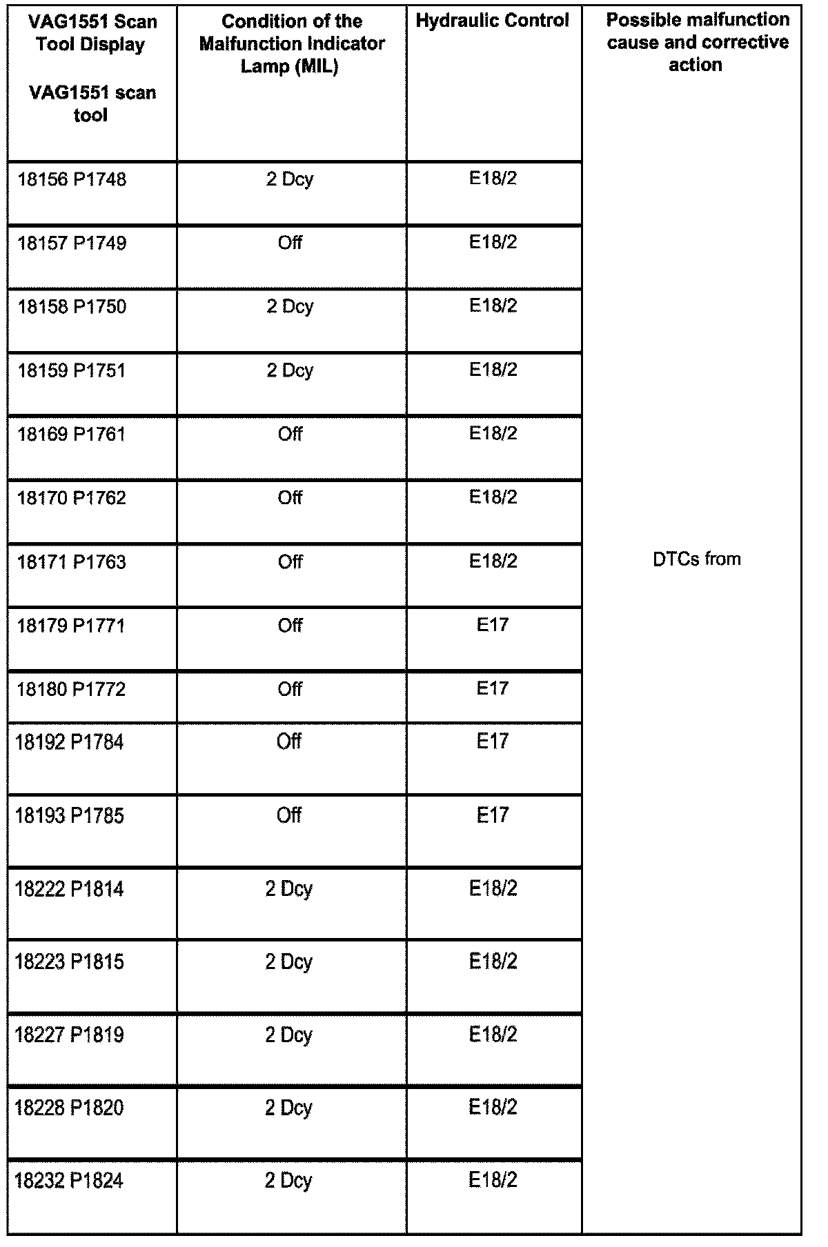
A L L Diagnostic Trouble Codes ( DTC )
- Testing and Inspection
- P Code Charts
- All Other P Codes
- P0010
- P0011
- P0012
- P0020
- P0021
- P0022
- P0102
- P0103
- P0106
- P0111
- P0112
- P0113
- P0116
- P0117
- P0118
- P0121
- P0130
- P0131
- P0132
- P0133
- P0134
- P0136
- P0137
- P0138
- P0139
- P0140
- P0150
- P0151
- P0152
- P0153
- P0154
- P0156
- P0157
- P0158
- P0159
- P0160
- P0196
- P0197
- P0198
- P0236
- P0237
- P0238
- P0300
- P0301
- P0302
- P0303
- P0304
- P0305
- P0306
- P0307
- P0308
- P0321
- P0322
- P0327
- P0328
- P0332
- P0333
- P0340
- P0341
- P0346
- P0420
- P0421
- P0422
- P0430
- P0431
- P0432
- P0441
- P0501
- P0506
- P0507
- P0560
- P0562
- P0563
- P0571
- P0601
- P0604
- P0605
- P0606
- P0685
- P0686
- P0687
- P0688
- P1008
- P1009
- P1020
- P1063
- P1065
- P1073
- P1074
- P1102
- P1105
- P1107
- P1110
- P1111
- P1112
- P1113
- P1114
- P1115
- P1116
- P1117
- P1118
- P1119
- P1120
- P1121
- P1122
- P1127
- P1128
- P1129
- P1130
- P1131
- P1136
- P1137
- P1138
- P1139
- P1140
- P1141
- P1142
- P1143
- P1147
- P1148
- P1149
- P1150
- P1159
- P1171
- P1172
- P1173
- P1176
- P1177
- P1198
- P1199
- P1200
- P1201
- P1202
- P1203
- P1204
- P1205
- P1206
- P1207
- P1208
- P1213
- P1214
- P1215
- P1216
- P1217
- P1218
- P1219
- P1220
- P1225
- P1226
- P1227
- P1228
- P1229
- P1230
- P1231
- P1232
- P1233
- P1237
- P1238
- P1239
- P1240
- P1241
- P1242
- P1243
- P1244
- P1250
- P1287
- P1288
- P1289
- P1297
- P1321
- P1322
- P1325
- P1326
- P1327
- P1328
- P1329
- P1330
- P1331
- P1332
- P1335
- P1336
- P1337
- P1338
- P1340
- P1347
- P1355
- P1356
- P1357
- P1358
- P1359
- P1360
- P1361
- P1362
- P1363
- P1364
- P1365
- P1366
- P1367
- P1368
- P1369
- P1370
- P1371
- P1372
- P1373
- P1374
- P1375
- P1376
- P1377
- P1378
- P1386
- P1387
- P1388
- P1391
- P1392
- P1409
- P1410
- P1411
- P1414
- P1420
- P1421
- P1422
- P1423
- P1424
- P1425
- P1426
- P1432
- P1433
- P1434
- P1435
- P1436
- P1453
- P1454
- P1455
- P1456
- P1457
- P1458
- P1459
- P1460
- P1461
- P1462
- P1500
- P1502
- P1517
- P1519
- P1522
- P1523
- P1525
- P1526
- P1527
- P1528
- P1529
- P1530
- P1531
- P1533
- P1534
- P1535
- P1536
- P1542
- P1543
- P1544
- P1545
- P1546
- P1547
- P1548
- P1555
- P1556
- P1557
- P1558
- P1559
- P1560
- P1564
- P1565
- P1568
- P1569
- P1570
- P1571
- P1572
- P1573
- P1575
- P1576
- P1577
- P1579
- P1602
- P1603
- P1604
- P1609
- P1612
- P1624
- P1626
- P1628
- P1630
- P1631
- P1633
- P1634
- P1635
- P1636
- P1639
- P1640
- P1648
- P1649
- P1650
- P1653
- P1654
- P1659
- P1660
- P1661
- P1662
- P1672
- P1682
- P1683
- P1687
- P1900
- P1931
- P1985
- P3011
- P3012
- P3041
- P3081
- P3262
- Manufacturer Code Charts
- Acoustic Parking System (APS)
- Air Bag Systems
- Anti-Theft
- Automatic Headlight Aim Control
- Brakes and Traction Control
- Engine Control System
- DTC 16152
- DTC 16153
- DTC 16154
- DTC 16394
- DTC 16395
- DTC 16396
- DTC 16404
- DTC 16405
- DTC 16406
- DTC 16486
- DTC 16487
- DTC 16490
- DTC 16495
- DTC 16496
- DTC 16497
- DTC 16500
- DTC 16501
- DTC 16502
- DTC 16514
- DTC 16515
- DTC 16516
- DTC 16517
- DTC 16518
- DTC 16520
- DTC 16521
- DTC 16522
- DTC 16523
- DTC 16524
- DTC 16534
- DTC 16535
- DTC 16540
- DTC 16541
- DTC 16542
- DTC 16543
- DTC 16544
- DTC 16580
- DTC 16581
- DTC 16582
- DTC 16620
- DTC 16621
- DTC 16622
- DTC 16684
- DTC 16685
- DTC 16686
- DTC 16687
- DTC 16688
- DTC 16689
- DTC 16690
- DTC 16691
- DTC 16692
- DTC 16705
- DTC 16706
- DTC 16711
- DTC 16712
- DTC 16716
- DTC 16717
- DTC 16724
- DTC 16725
- DTC 16730
- DTC 16804
- DTC 16805
- DTC 16806
- DTC 16814
- DTC 16815
- DTC 16816
- DTC 16825
- DTC 16885
- DTC 16890
- DTC 16891
- DTC 16946
- DTC 16947
- DTC 16955
- DTC 16985
- DTC 16988
- DTC 16989
- DTC 16990
- DTC 17069
- DTC 17070
- DTC 17071
- DTC 17072
- DTC 17416
- DTC 17417
- DTC 17428
- DTC 17471
- DTC 17473
- DTC 17481
- DTC 17482
- DTC 17510
- DTC 17513
- DTC 17515
- DTC 17518
- DTC 17519
- DTC 17520
- DTC 17521
- DTC 17522
- DTC 17523
- DTC 17524
- DTC 17525
- DTC 17526
- DTC 17527
- DTC 17528
- DTC 17529
- DTC 17530
- DTC 17535
- DTC 17536
- DTC 17537
- DTC 17538
- DTC 17539
- DTC 17544
- DTC 17545
- DTC 17546
- DTC 17547
- DTC 17548
- DTC 17549
- DTC 17550
- DTC 17551
- DTC 17555
- DTC 17556
- DTC 17557
- DTC 17558
- DTC 17567
- DTC 17569
- DTC 17580
- DTC 17581
- DTC 17584
- DTC 17585
- DTC 17606
- DTC 17607
- DTC 17608
- DTC 17609
- DTC 17610
- DTC 17611
- DTC 17612
- DTC 17613
- DTC 17614
- DTC 17615
- DTC 17616
- DTC 17621
- DTC 17622
- DTC 17623
- DTC 17624
- DTC 17625
- DTC 17626
- DTC 17627
- DTC 17628
- DTC 17633
- DTC 17634
- DTC 17635
- DTC 17636
- DTC 17637
- DTC 17638
- DTC 17639
- DTC 17640
- DTC 17641
- DTC 17645
- DTC 17646
- DTC 17647
- DTC 17648
- DTC 17649
- DTC 17650
- DTC 17651
- DTC 17652
- DTC 17658
- DTC 17695
- DTC 17696
- DTC 17697
- DTC 17705
- DTC 17729
- DTC 17730
- DTC 17733
- DTC 17734
- DTC 17735
- DTC 17736
- DTC 17737
- DTC 17738
- DTC 17739
- DTC 17740
- DTC 17743
- DTC 17744
- DTC 17745
- DTC 17746
- DTC 17748
- DTC 17755
- DTC 17763
- DTC 17764
- DTC 17765
- DTC 17766
- DTC 17767
- DTC 17768
- DTC 17769
- DTC 17770
- DTC 17771
- DTC 17772
- DTC 17773
- DTC 17774
- DTC 17775
- DTC 17776
- DTC 17777
- DTC 17778
- DTC 17779
- DTC 17780
- DTC 17781
- DTC 17782
- DTC 17783
- DTC 17784
- DTC 17785
- DTC 17786
- DTC 17794
- DTC 17795
- DTC 17796
- DTC 17799
- DTC 17800
- DTC 17817
- DTC 17818
- DTC 17819
- DTC 17822
- DTC 17828
- DTC 17829
- DTC 17830
- DTC 17831
- DTC 17832
- DTC 17833
- DTC 17834
- DTC 17840
- DTC 17841
- DTC 17842
- DTC 17843
- DTC 17844
- DTC 17861
- DTC 17862
- DTC 17863
- DTC 17864
- DTC 17865
- DTC 17866
- DTC 17867
- DTC 17868
- DTC 17869
- DTC 17870
- DTC 17908
- DTC 17910
- DTC 17925
- DTC 17927
- DTC 17930
- DTC 17931
- DTC 17933
- DTC 17934
- DTC 17935
- DTC 17936
- DTC 17937
- DTC 17938
- DTC 17939
- DTC 17941
- DTC 17942
- DTC 17943
- DTC 17944
- DTC 17950
- DTC 17951
- DTC 17952
- DTC 17953
- DTC 17954
- DTC 17955
- DTC 17956
- DTC 17963
- DTC 17964
- DTC 17965
- DTC 17966
- DTC 17967
- DTC 17968
- DTC 17972
- DTC 17973
- DTC 17976
- DTC 17977
- DTC 17978
- DTC 17979
- DTC 17980
- DTC 17981
- DTC 17983
- DTC 17984
- DTC 17985
- DTC 17987
- DTC 18010
- DTC 18011
- DTC 18012
- DTC 18017
- DTC 18020
- DTC 18032
- DTC 18034
- DTC 18036
- DTC 18038
- DTC 18039
- DTC 18041
- DTC 18042
- DTC 18043
- DTC 18044
- DTC 18047
- DTC 18048
- DTC 18056
- DTC 18057
- DTC 18058
- DTC 18062
- DTC 18067
- DTC 18068
- DTC 18069
- DTC 18070
- DTC 18080
- DTC 18090
- DTC 18091
- DTC 18095
- DTC 18261
- DTC 18308
- DTC 18339
- DTC 18393
- DTC 19437
- DTC 19467
- DTC 19468
- DTC 19497
- DTC 19718
- Heating and Air Conditioning
- About Trouble Codes
- P Codes
- VAG Codes
- DTC 00000
- DTC 00532
- DTC 00538
- DTC 00601
- DTC 00604
- DTC 00624
- DTC 00625
- DTC 00710
- DTC 00716
- DTC 00727
- DTC 00735
- DTC 00756
- DTC 00757
- DTC 00779
- DTC 00785
- DTC 00787
- DTC 00792
- DTC 00796
- DTC 00797
- DTC 00818
- DTC 00819
- DTC 00975
- DTC 01044
- DTC 01087
- DTC 01206
- DTC 01232
- DTC 01270
- DTC 01272
- DTC 01273
- DTC 01274
- DTC 01297
- DTC 01312
- DTC 01314
- DTC 01317
- DTC 01582
- DTC 01592
- DTC 01593
- DTC 01809
- DTC 01810
- DTC 01841
- DTC 01842
- DTC 65535
- Output Diagnostic Test Mode (DTM) (Function 03)
- Measuring Value Blocks (Function 08)
- Reading
- Overview Of Selectable Display Group Numbers
- Display Group 001
- Display Group 002
- Display Group 003
- Display Group 004
- Display Group 005
- Display Group 006
- Display Group 007
- Display Group 008
- Display Group 009
- Display Group 010
- Display Group 011
- Display Group 012
- Display Group 013
- Display Group 014
- Display Group 015
- Display Group 016
- Display Group 017
- Display Group 018
- Display Group 019
- Display Groups Currently Not to Be Used By Dealerships
- Component Testing
- Instrument Cluster/Carrier
- Power Locks
- About Trouble Codes
- VAG Codes
- DTC 00668
- DTC 00849
- DTC 00947
- DTC 00951
- DTC 00952
- DTC 00955
- DTC 00956
- DTC 00957
- DTC 00958
- DTC 00991
- DTC 01141
- DTC 01366
- DTC 01368
- DTC 01369
- DTC 01370
- DTC 01371
- DTC 01373
- DTC 01374
- DTC 01389
- DTC 01403
- DTC 01482
- DTC 01557
- DTC 01558
- DTC 01559
- DTC 01560
- DTC 01561
- DTC 01562
- DTC 01563
- DTC 01564
- DTC 01565
- DTC 01566
- DTC 01568
- DTC 01569
- DTC 01570
- DTC 01571
- DTC 01572
- DTC 01573
- DTC 01574
- DTC 01581
- DTC 01585
- DTC 01586
- DTC 65535
- Output Diagnostic Test Mode (DTM) (Function 03)
- Measuring Value Blocks (Function 08)
- Power Seats
- Ultrasonic Interior Monitoring
- Related Tests, Information and Procedures
- P Code Charts