P0727

Factory Manual References

Factory service manual diagnostic procedure for 2002 audi s4

5 Spd. Automatic Transmission 01V


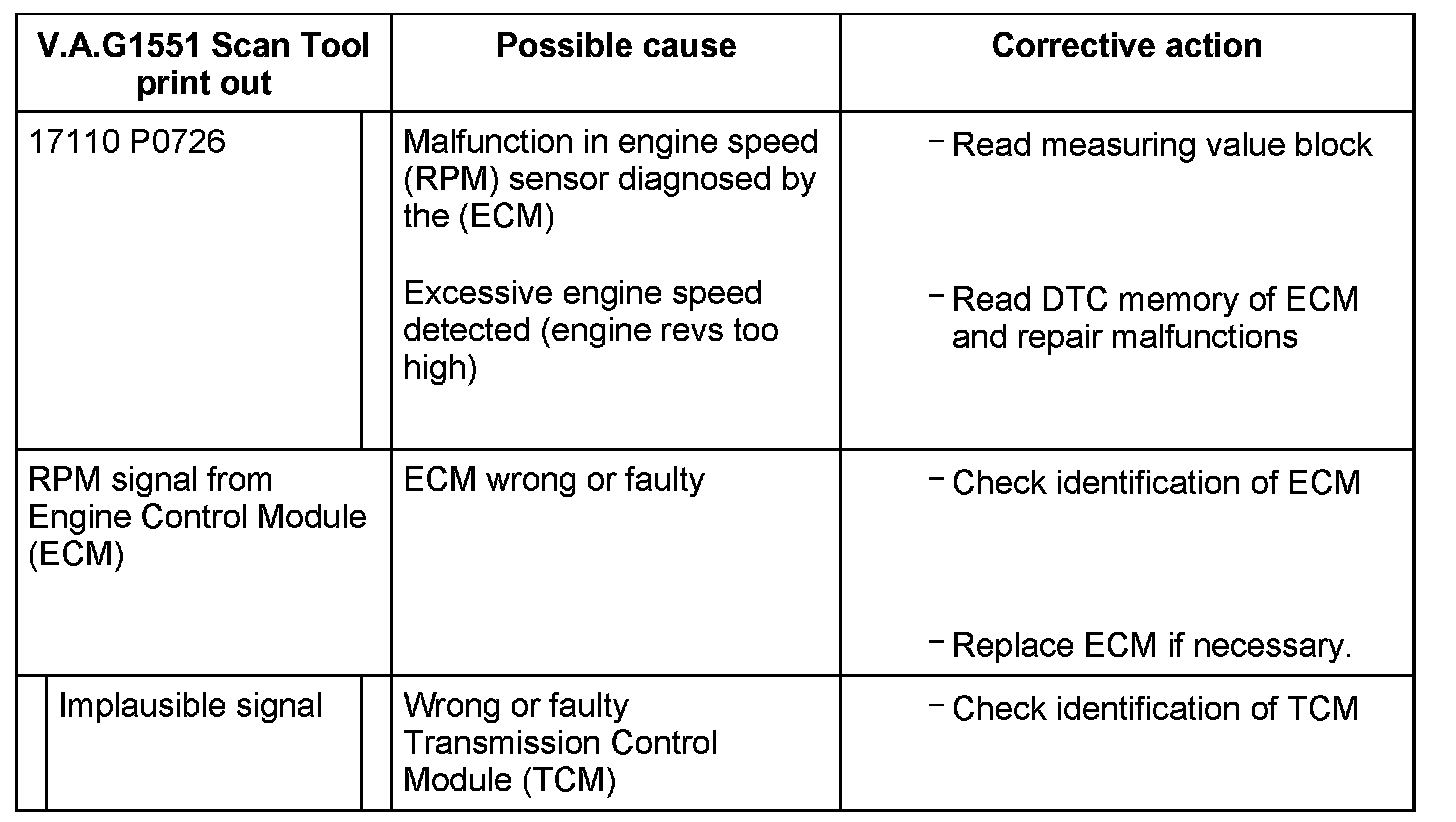
Diagnostic Trouble Codes 00543 / P0726 and 17110 / P0726 - 5 Spd. Automatic Transmission 01V

Factory service manual diagram


1) Pay attention to which hydraulic control the transmission has when selecting measuring value block.
2) Notes and conditions for malfunction recognition, see DTC 00529 / P0727 (RPM information missing)

Factory service manual diagram


1) Pay attention to which hydraulic control the transmission has when selecting measuring value block.
2) Notes and conditions for malfunction recognition, see DTC 00529 / P0727 (RPM information missing)

Factory service manual diagram


1) Pay attention to which hydraulic control the transmission has when selecting measuring value block.

Note for DTC 17110 / P0726:

^ The engine speed signal is transmitted by the Engine Control Module (ECM) to the Transmission Control Module (TCM) via the CAN-bus wiring.

01V, 5 Speed A/T

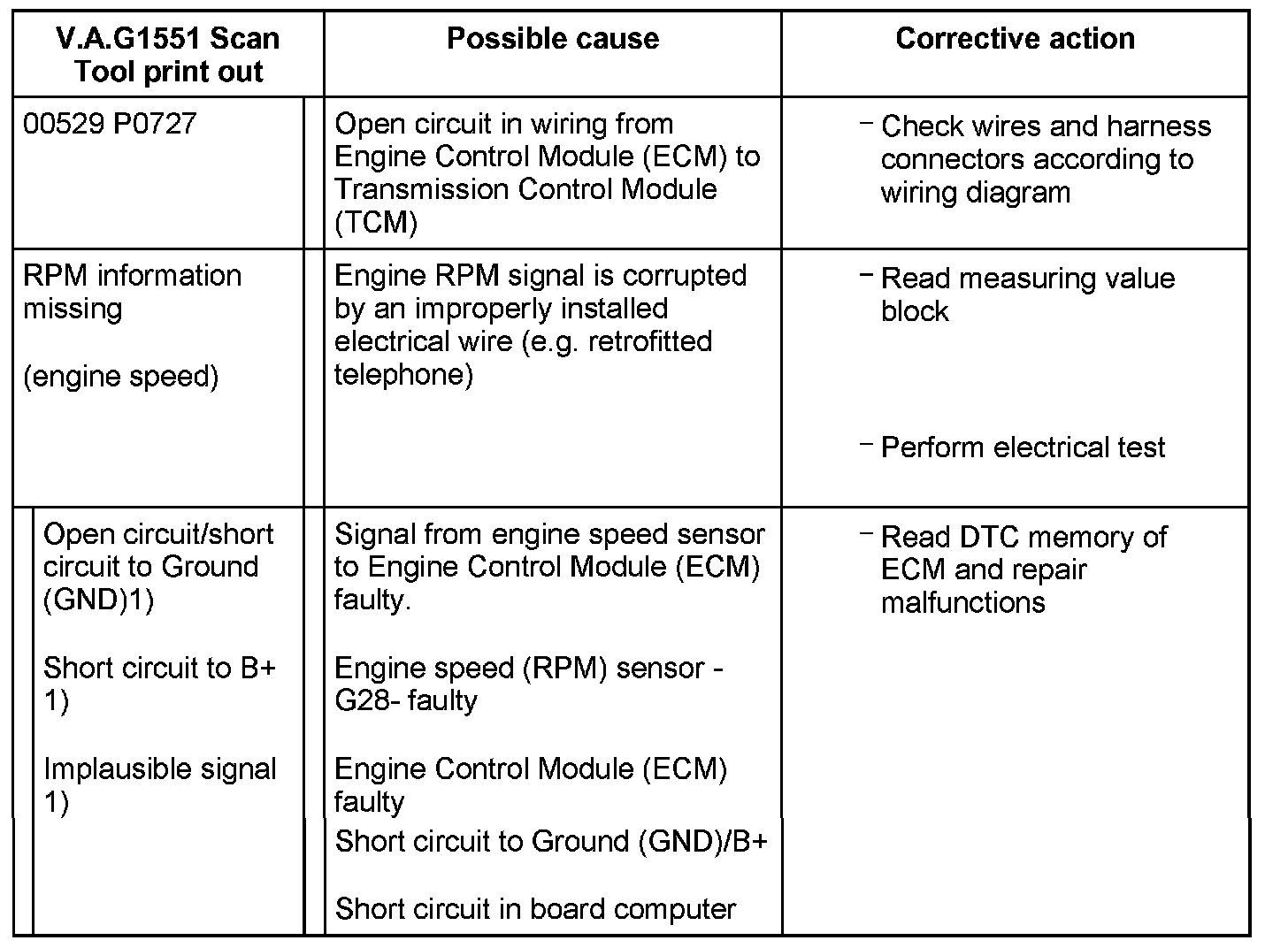
DTC P0727:

Factory service manual diagram


DTC P0727:

Factory service manual diagram


5 Spd. Automatic Transmission 01V


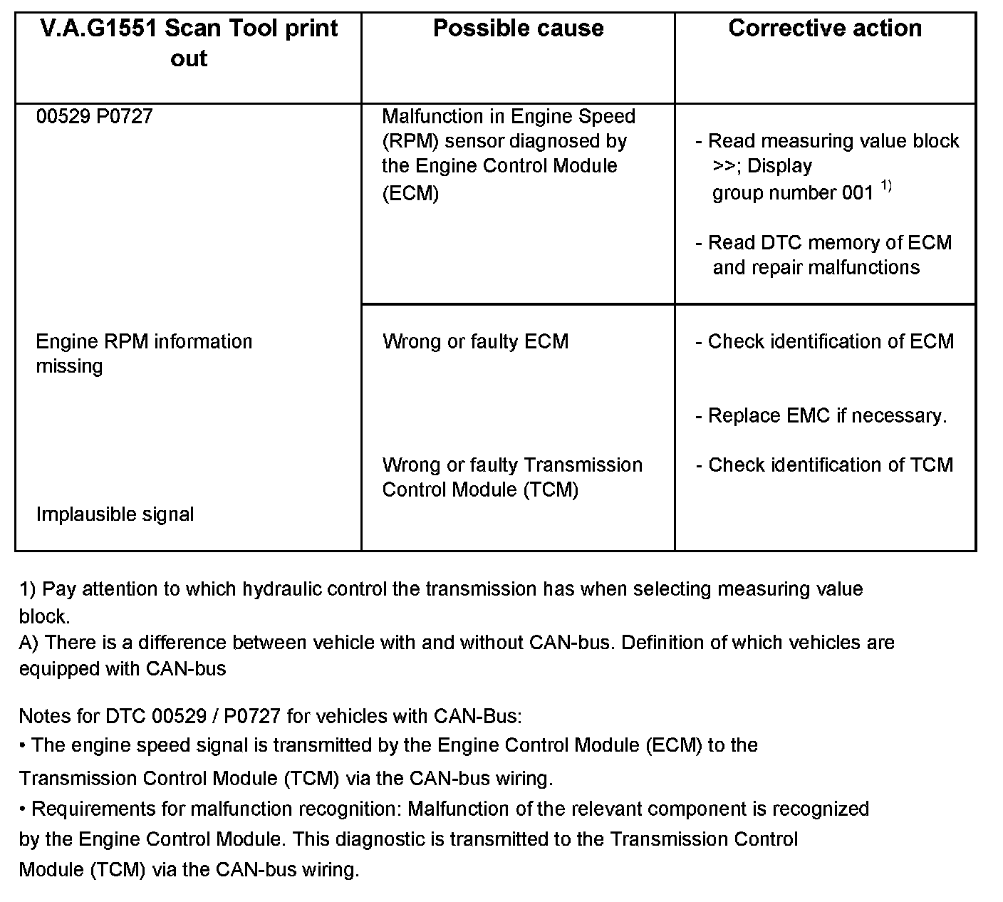
Diagnostic Trouble Codes 00529 / P0727 - 5 Spd. Automatic Transmission 01V

DTC 00529 / P0727 for vehicles with CAN-Bus A)

Factory service manual diagram


1) Pay attention to which hydraulic control the transmission has when selecting measuring value block.
A) There is a difference between vehicle with and without CAN-bus.

Note for DTC 00529 / P0727 for vehicles with CAN-Bus:

^ The engine speed signal is transmitted by the Engine Control Module (ECM) to the Transmission Control Module (TCM) via the CAN-bus wiring.
^ Requirements for malfunction recognition: Malfunction of the relevant component is recognized by the Engine Control Module. This diagnostic is transmitted to the Transmission Control Module (TCM) via the CAN-bus wiring.

DTC 00529 / P0727 for vehicles without CAN-Bus A)

Factory service manual diagram


1) One of these indications is also displayed for the relevant component.
2) Pay attention to which hydraulic control the transmission has when selecting measuring value block.
A) There is a difference between vehicles with and without CAN-bus.

Note for DTC 00529 / P0727 for vehicle types without CAN-Bus A):

^ Malfunction recognition of DTC 00529 / PO727 by the TCM is much more sensitive than detection by the ECM. This means that a brief interruption in the throttle position signal (up to 1 second) is not detected by the ECM, but is registered as a malfunction by the TCM.
^ Malfunction detection for DTC 00529 / PO727 is based on a plausibility test relating the signal to the fuel consumption signal (or if not installed to throttle position value).
^ Requirements for malfunction recognition- Multi-function TR switch -F125- OK, fuel consumption signal or throttle position signal OK, recognized value for transmission RPM above 200 RPM and 200 ms no engine RPM signal at Transmission Control Module (TCM).

Supporting Diagrams & Locations

Reference material from the factory manual for this diagnostic procedure.

Diagram

2.7L Turbo

Diagram

2.7L Turbo

Diagram

2.7L Turbo

Diagram

2.7L Turbo

Location

1.8L (Engine Code: AMB)

Location

2.0L (Engine Codes: BGP, BWT)

Location

2.7L (2002 S4 - Engine Code: APB)

Location

3.0L (Engine Codes: AVK, BGN)

Related Procedures

Procedure

Aftermarket (Non-AUDI Brand) MOTOROLA V60 Phones, Installation Caution (GROUP 91, NO. 02-09)

Procedure

Aftermarket (Non-AUDI Brand) MOTOROLA V60 Phones, Installation Caution (GROUP 91, NO. 02-09)

Procedure

Aftermarket (Non-AUDI Brand) MOTOROLA V60 Phones, Installation Caution (GROUP 91, NO. 02-09)

Procedure

Aftermarket (Non-AUDI Brand) MOTOROLA V60 Phones, Installation Caution (GROUP 91, NO. 02-09)