
Safety Warning
DIY auto repair can cause serious injury, fire, or vehicle damage. These guides are for informational purposes only. Always follow OEM torque specs, wear PPE, and consult a certified mechanic if you are unsure. You are solely responsible for your safety.
1993 Volvo 850 L5-2.4L VIN 55 B5254SFACTORY OEM SERVICE PROCEDURE
Engine Is Difficult to Start
ENGINE IS DIFFICULT TO START
Conditions for Fault Tracing
^ No DTCs present.
^ Engine hot.
Fault sources
^ Contact resistance in Engine Speed (RPM) Sensor connector.
^ Faulty RPM Sensor.
^ Contact resistance in Camshaft Position (CMP) Sensor connector.
^ Leaking Exhaust Gas Recirculation (EGR) Valve.
^ Leaking EGR Controller.
^ Contact resistance in Engine Coolant Temperature (ECT) Sensor connector.
^ Faulty ECT Sensor.
^ Faulty or damaged Spark Plug and/or Ignition Lead.
^ Faulty Distributor Cap and/or Rotor.
^ Incorrect fuel pressure or residual fuel pressure.
^ Contact resistance in Ignition Systems' (DI) Power Stage connector.
TESTING PROCEDURE
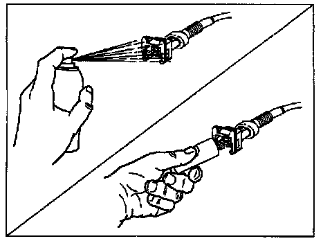
Cleaning and Greasing of Control Module Connectors
^ Switch off ignition.
^ Remove both control modules, (MFI and ICM).
Located on the right side of the engine compartment, inside the Control Module Box.
MFI = LH 3.2 Engine Control Module
ICM = EZK 129 Ignition Control Module
^ Check control module connectors for contact resistance and oxidation.
^ Reinstall both control modules.
When connectors have been checked:
- Proceed to: Cleaning and Greasing ECT Sensor Connector.
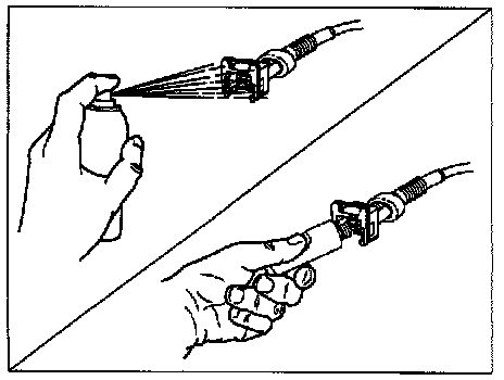
Cleaning and Greasing of ECT Sensor Connector
^ Switch OFF Ignition.
^ Disconnect sensor.
^ Check sensor connector for contact resistance and oxidation.
^ Reconnect sensor.
When connector has been checked:
- Proceed to: Checking Engine Temperature.
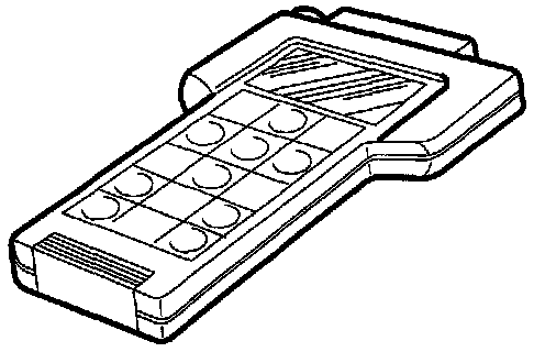
Checking Engine Temperature
^ Switch ON Ignition.
^ Check that value of engine coolant temperature (ECT) is reasonable.
Temperature should be over 75°C (167°F) when engine is hot, upper coolant hose is hot and thermostat is fully open.
If value is correct:
- Proceed to: Cleaning and Greasing CMP Sensor Connector.
If value is incorrect:
- Try with new sensor.
- Proceed to: Cleaning and Greasing CMP Sensor Connector.
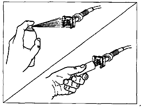
Cleaning and Greasing of CMP Sensor Connector
^ Switch OFF Ignition.
^ Disconnect sensor.
^ Check sensor connector for contact resistance and oxidation.
^ Reconnect sensor.
When connector has been checked:
- Proceed to: Cleaning and Greasing RPM Sensor Connector.
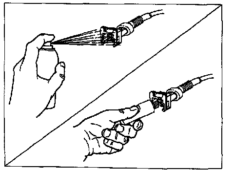
Cleaning and Greasing of RPM Sensor Connector
^ Switch OFF Ignition.
^ Disconnect sensor.
^ Check sensor connector for contact resistance and oxidation.
When connector has been checked:
- Proceed to: Checking RPM Sensor.
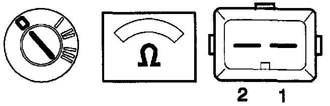
Checking RPM Sensor
^ Switch OFF Ignition.
^ Disconnect sensor.
^ Connect ohmmeter between sensor connector terminals 1 and 2.
Instrument should indicate 200 - 400 ohms depending on engine temperature.
If reading is correct:
- Proceed to: Cleaning and Greasing DI Power Stage Connector.
If reading is incorrect:
- Try with new sensor.
- Proceed to: Cleaning and Greasing Power Stage Connector.

Cleaning and Greasing of DI Power Stage Connector
^ Switch OFF Ignition.
^ Reconnect RPM sensor.
^ Check power stage connector for contact resistance and oxidation.
^ Reconnect power stage.
When connector has been checked:
- Proceed to: Checking Ignition Coil Primary Winding.

Checking Ignition Coil Primary Winding
^ Switch OFF Ignition.
^ Disconnect one ignition coil lead.
^ Connect ohmmeter between primary winding terminals (1 and 15).
Instrument should indicate 0.5 - 1.5 ohms.
If reading is correct:
- Proceed to: Checking Ignition Coil Secondary Winding.
If reading is incorrect:
- Try with new ignition coil.
- Proceed to: Checking Distributor Cap, Distributor Rotor and Ignition Leads, section below.

Checking Ignition Coil Secondary Winding
^ Switch OFF Ignition.
^ Disconnect coil high-tension lead (king lead).
^ Connect ohmmeter between terminal 15 and high-tension terminal.
Instrument should indicate approx. 8 - 9K ohms.
If reading is correct:
- Proceed to: Checking Distributor Cap, Distributor Rotor and Ignition Leads.
If reading is incorrect:
- Try with new ignition coil.
- Proceed to: Checking of Distributor Cap, Rotor and Ignition Leads.
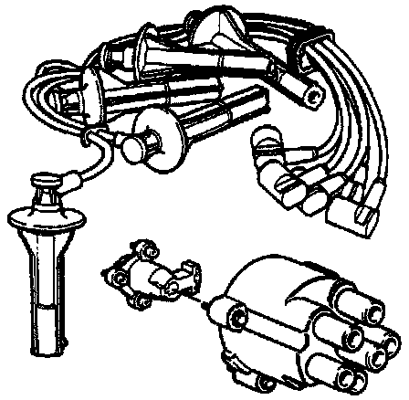
Checking Distributor Cap, Distributor Rotor and Ignition Leads
^ Switch OFF Ignition.
^ Check distributor cap, distributor rotor and ignition leads for damage, cracks and arcing.
If fault is suspected:
- Clean parts suspected of being damaged / faulty or replace as required.
- Reinstall distributor cap and rotor.
- Proceed to: Checking Spark Plugs.

Checking Spark Plugs
^ Switch OFF Ignition.
^ Replace all spark plugs.
^ Reconnect all ignition leads.
Check Fuel Pressure and Residual Fuel Pressure.
- See: FUEL DELIVERY AND AIR INDUCTION / FUEL PRESSURE / TESTING AND INSPECTION.
Conditions for Fault Tracing
^ No DTCs present.
^ Engine hot.
Fault sources
^ Contact resistance in Engine Speed (RPM) Sensor connector.
^ Faulty RPM Sensor.
^ Contact resistance in Camshaft Position (CMP) Sensor connector.
^ Leaking Exhaust Gas Recirculation (EGR) Valve.
^ Leaking EGR Controller.
^ Contact resistance in Engine Coolant Temperature (ECT) Sensor connector.
^ Faulty ECT Sensor.
^ Faulty or damaged Spark Plug and/or Ignition Lead.
^ Faulty Distributor Cap and/or Rotor.
^ Incorrect fuel pressure or residual fuel pressure.
^ Contact resistance in Ignition Systems' (DI) Power Stage connector.
TESTING PROCEDURE
Cleaning and Greasing of Control Module Connectors
^ Switch off ignition.
^ Remove both control modules, (MFI and ICM).
Located on the right side of the engine compartment, inside the Control Module Box.
MFI = LH 3.2 Engine Control Module
ICM = EZK 129 Ignition Control Module
^ Check control module connectors for contact resistance and oxidation.
^ Reinstall both control modules.
When connectors have been checked:
- Proceed to: Cleaning and Greasing ECT Sensor Connector.
Cleaning and Greasing of ECT Sensor Connector
^ Switch OFF Ignition.
^ Disconnect sensor.
^ Check sensor connector for contact resistance and oxidation.
^ Reconnect sensor.
When connector has been checked:
- Proceed to: Checking Engine Temperature.
Checking Engine Temperature
^ Switch ON Ignition.
^ Check that value of engine coolant temperature (ECT) is reasonable.
Temperature should be over 75°C (167°F) when engine is hot, upper coolant hose is hot and thermostat is fully open.
If value is correct:
- Proceed to: Cleaning and Greasing CMP Sensor Connector.
If value is incorrect:
- Try with new sensor.
- Proceed to: Cleaning and Greasing CMP Sensor Connector.
Cleaning and Greasing of CMP Sensor Connector
^ Switch OFF Ignition.
^ Disconnect sensor.
^ Check sensor connector for contact resistance and oxidation.
^ Reconnect sensor.
When connector has been checked:
- Proceed to: Cleaning and Greasing RPM Sensor Connector.
Cleaning and Greasing of RPM Sensor Connector
^ Switch OFF Ignition.
^ Disconnect sensor.
^ Check sensor connector for contact resistance and oxidation.
When connector has been checked:
- Proceed to: Checking RPM Sensor.
Checking RPM Sensor
^ Switch OFF Ignition.
^ Disconnect sensor.
^ Connect ohmmeter between sensor connector terminals 1 and 2.
Instrument should indicate 200 - 400 ohms depending on engine temperature.
If reading is correct:
- Proceed to: Cleaning and Greasing DI Power Stage Connector.
If reading is incorrect:
- Try with new sensor.
- Proceed to: Cleaning and Greasing Power Stage Connector.
Cleaning and Greasing of DI Power Stage Connector
^ Switch OFF Ignition.
^ Reconnect RPM sensor.
^ Check power stage connector for contact resistance and oxidation.
^ Reconnect power stage.
When connector has been checked:
- Proceed to: Checking Ignition Coil Primary Winding.
Checking Ignition Coil Primary Winding
^ Switch OFF Ignition.
^ Disconnect one ignition coil lead.
^ Connect ohmmeter between primary winding terminals (1 and 15).
Instrument should indicate 0.5 - 1.5 ohms.
If reading is correct:
- Proceed to: Checking Ignition Coil Secondary Winding.
If reading is incorrect:
- Try with new ignition coil.
- Proceed to: Checking Distributor Cap, Distributor Rotor and Ignition Leads, section below.
Checking Ignition Coil Secondary Winding
^ Switch OFF Ignition.
^ Disconnect coil high-tension lead (king lead).
^ Connect ohmmeter between terminal 15 and high-tension terminal.
Instrument should indicate approx. 8 - 9K ohms.
If reading is correct:
- Proceed to: Checking Distributor Cap, Distributor Rotor and Ignition Leads.
If reading is incorrect:
- Try with new ignition coil.
- Proceed to: Checking of Distributor Cap, Rotor and Ignition Leads.
Checking Distributor Cap, Distributor Rotor and Ignition Leads
^ Switch OFF Ignition.
^ Check distributor cap, distributor rotor and ignition leads for damage, cracks and arcing.
If fault is suspected:
- Clean parts suspected of being damaged / faulty or replace as required.
- Reinstall distributor cap and rotor.
- Proceed to: Checking Spark Plugs.
Checking Spark Plugs
^ Switch OFF Ignition.
^ Replace all spark plugs.
^ Reconnect all ignition leads.
Check Fuel Pressure and Residual Fuel Pressure.
- See: FUEL DELIVERY AND AIR INDUCTION / FUEL PRESSURE / TESTING AND INSPECTION.
Factory Service Tools
Use the Manual With the Right Hardware
Pair factory procedures with proven DIY tools so the instructions are easier to execute.
Disclosure: Verified tool recommendations may earn an affiliate commission at no cost to you.
When to See a Mechanic
Stop DIY work and contact a certified mechanic immediately if any of the following apply:
- • You smell fuel, burning insulation, or see smoke.
- • Brakes feel soft, pull hard to one side, or make grinding noises.
- • The engine overheats, stalls repeatedly, or misfires under load.
- • You are missing required tools, torque specs, or safe lifting equipment.
- • You are not confident in the next step or safety outcome.
Rather have a pro handle this?
A certified mobile mechanic comes to your home or office. They bring the tools, you stay comfortable. No tow truck, no waiting room, no surprises.
Comes to youSame-day available12-month warranty
Get a Free QuoteNo obligation. See pricing before you book.