
Safety Warning
DIY auto repair can cause serious injury, fire, or vehicle damage. These guides are for informational purposes only. Always follow OEM torque specs, wear PPE, and consult a certified mechanic if you are unsure. You are solely responsible for your safety.
1993 Volvo 850 L5-2.4L VIN 55 B5254SFACTORY OEM SERVICE PROCEDURE
Replacing Control Module Box
Removal:
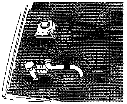
- Ignition off.
- Remove front air duct to control module box.
- Remove filler pipe from washer fluid reservoir.
- Undo expansion tank and pull upwards.
- Undo DLC (Data Link Connector).
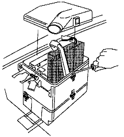
Remove:
- Control module box cover (pry metal clip open with screwdriver).
- Control modules from control module box.
- Front mounting screw.
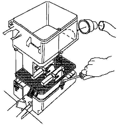
Remove:
- Center section of control module box, pry metal clips (3 x) open with screwdriver.
- Connecting stub to control module box air intake.
- Lift control module holder and cable duct so it comes clear of clips.

Remove:
- Undo connector at base of control module box.
- Cable tie screws on side of control module box.
- Pull up lead on side of control module box.
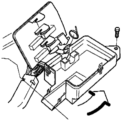
Remove:
- Rear mounting screw.
- Lower section of control module box. Pull it backwards until it comes free from the body plate flap at the front of the control module box.
- Cable tie at side of control module box.
Installation:

Install:
- Cable tie on side of control module box.
- Lower section of control module box, inserting it at the front, under the body plate flap.
- Rear mounting screw.

Install:
- Connector in base of control module box.
- Lead on side of control module box.
- Screws to cable tie on side of control module box.
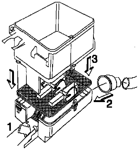
Install:
- Control module holder. Make sure catches lock.
- Cable duct, insert into track in control module box.
- Connecting stub to control module box air intake.
- Center section of control module box.
Check that center and lower sections of control module box fit tightly and that clips lock properly.
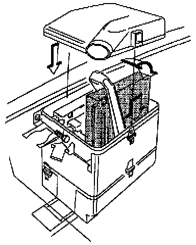
Install:
- Front mounting screw.
- Control modules.
- Control module box cover; check that clips lock properly.
Install:
- DLC (Data Link Connector).
- Filler pipe to washer fluid reservoir.
- Check that filler pipe fits right to reservoir
- Front air duct to control module box.
- Expansion tank.
- Ignition off.
- Remove front air duct to control module box.
- Remove filler pipe from washer fluid reservoir.
- Undo expansion tank and pull upwards.
- Undo DLC (Data Link Connector).
Remove:
- Control module box cover (pry metal clip open with screwdriver).
- Control modules from control module box.
- Front mounting screw.
Remove:
- Center section of control module box, pry metal clips (3 x) open with screwdriver.
- Connecting stub to control module box air intake.
- Lift control module holder and cable duct so it comes clear of clips.
Remove:
- Undo connector at base of control module box.
- Cable tie screws on side of control module box.
- Pull up lead on side of control module box.
Remove:
- Rear mounting screw.
- Lower section of control module box. Pull it backwards until it comes free from the body plate flap at the front of the control module box.
- Cable tie at side of control module box.
Installation:
Install:
- Cable tie on side of control module box.
- Lower section of control module box, inserting it at the front, under the body plate flap.
- Rear mounting screw.
Install:
- Connector in base of control module box.
- Lead on side of control module box.
- Screws to cable tie on side of control module box.
Install:
- Control module holder. Make sure catches lock.
- Cable duct, insert into track in control module box.
- Connecting stub to control module box air intake.
- Center section of control module box.
Check that center and lower sections of control module box fit tightly and that clips lock properly.
Install:
- Front mounting screw.
- Control modules.
- Control module box cover; check that clips lock properly.
Install:
- DLC (Data Link Connector).
- Filler pipe to washer fluid reservoir.
- Check that filler pipe fits right to reservoir
- Front air duct to control module box.
- Expansion tank.
Factory Service Tools
Use the Manual With the Right Hardware
Pair factory procedures with proven DIY tools so the instructions are easier to execute.
Disclosure: Verified tool recommendations may earn an affiliate commission at no cost to you.
When to See a Mechanic
Stop DIY work and contact a certified mechanic immediately if any of the following apply:
- • You smell fuel, burning insulation, or see smoke.
- • Brakes feel soft, pull hard to one side, or make grinding noises.
- • The engine overheats, stalls repeatedly, or misfires under load.
- • You are missing required tools, torque specs, or safe lifting equipment.
- • You are not confident in the next step or safety outcome.
Rather have a pro handle this?
A certified mobile mechanic comes to your home or office. They bring the tools, you stay comfortable. No tow truck, no waiting room, no surprises.
Comes to youSame-day available12-month warranty
Get a Free QuoteNo obligation. See pricing before you book.