
Safety Warning
DIY auto repair can cause serious injury, fire, or vehicle damage. These guides are for informational purposes only. Always follow OEM torque specs, wear PPE, and consult a certified mechanic if you are unsure. You are solely responsible for your safety.
2012 Toyota Venza FWD V6-3.5L (2GR-FE)FACTORY OEM SERVICE PROCEDURE
Part 1
U660E AUTOMATIC TRANSMISSION / TRANSAXLE: AUTOMATIC TRANSAXLE UNIT: DISASSEMBLY
1. REMOVE BREATHER PLUG HOSE
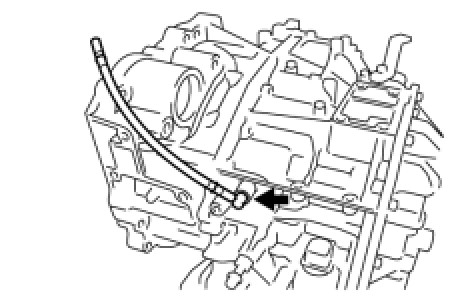
(a) Using a screwdriver, remove the breather plug hose from the transaxle case.
(b) Using a screwdriver, remove the No. 1 breather plug (ATM) and No. 2 breather plug (ATM) from the breather plug hose.
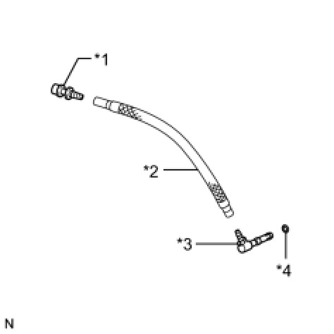
Text in Illustration

(c) Using a screwdriver, remove the O-ring from the No. 2 breather plug (ATM).
2. REMOVE PARK/NEUTRAL POSITION SWITCH ASSEMBLY
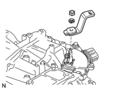
(a) Remove the nut, washer and control shaft lever from the control shaft.
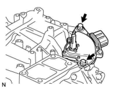
(b) Remove the 2 bolts and park/neutral position switch assembly from the transaxle case.
NOTICE:
Before removing the park/neutral position switch, remove any dirt or rust on the installation portion of the control shaft. Be sure to remove the switch straight along the shaft while being careful not to deform the plate spring that supports the shaft. If the plate spring is deformed, the park/neutral position switch cannot be reinstalled correctly.
3. REMOVE OIL COOLER TUBE UNION (OUTLET OIL COOLER UNION)
(a) Remove the oil cooler tube union (outlet oil cooler union) from the transaxle case.

(b) Remove the O-ring from the oil cooler tube union (outlet oil cooler union).
4. REMOVE OIL COOLER TUBE UNION (INLET OIL COOLER UNION)
(a) Loosen the nut while holding the oil cooler tube union (inlet oil cooler union).

(b) Remove the oil cooler tube union (inlet oil cooler union) from the transaxle case.
(c) Remove the O-ring from the oil cooler tube union (inlet oil cooler union).
5. REMOVE NO. 1 TRANSAXLE CASE PLUG
(a) Remove the 3 No. 1 transaxle case plugs from the transaxle case.

(b) Using a screwdriver, remove the 3 O-rings from the 3 No. 1 transaxle case plugs.
(c) Using a hexagon wrench (6 mm), remove the 3 hexagon bolts from the transaxle housing.

(d) Remove the gasket from each of the 3 hexagon bolts.
6. SUPPORT AUTOMATIC TRANSAXLE ASSEMBLY
(a) Support the transaxle assembly on wooden blocks.

7. REMOVE AUTOMATIC TRANSAXLE OIL PAN SUB-ASSEMBLY
(a) Using a hexagon wrench (6 mm), remove the overflow plug from the automatic transaxle oil pan sub-assembly.

(b) Remove the gasket from the overflow plug.
(c) Using a hexagon wrench (6 mm), remove the No. 1 transmission oil filler tube from the automatic transaxle assembly.
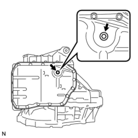
(d) Remove the 18 bolts, automatic transaxle oil pan sub-assembly and automatic transaxle oil pan gasket from the automatic transaxle assembly.
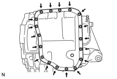
(e) Remove the 2 transmission oil cleaner magnets from the automatic transaxle oil pan sub-assembly.

Text in Illustration

8. INSPECT TRANSMISSION OIL CLEANER MAGNET Transaxle Unit
9. REMOVE VALVE BODY OIL STRAINER ASSEMBLY
(a) Remove the 2 bolts and oil strainer assembly from the valve body assembly.

(b) Remove the O-ring from the oil strainer assembly.

Text in Illustration

10. REMOVE TRANSMISSION VALVE BODY ASSEMBLY
(a) Remove the 11 bolts and valve body assembly from the transaxle case.

NOTICE:
When removing the transmission valve body assembly, be careful not to allow the transmission revolution sensor and the transaxle case to interfere with each other.
11. REMOVE TRANSAXLE CASE GASKET
(a) Remove the 2 gaskets from the transaxle case.
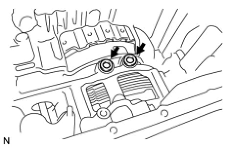
12. INSPECT INPUT SHAFT SUB-ASSEMBLY Transaxle Unit
13. REMOVE REAR TRANSAXLE COVER SUB-ASSEMBLY
(a) Remove the refill plug from the rear transaxle cover sub-assembly.
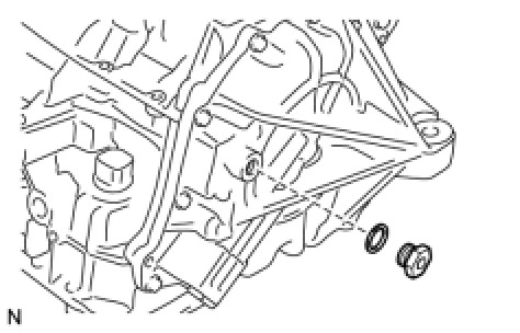
(b) Remove the gasket from the refill plug.
(c) Remove the 2 No. 1 automatic transaxle case plugs from the rear transaxle cover sub-assembly.

(d) Using a screwdriver, remove the 2 O-rings from the 2 No. 1 automatic transaxle case plugs.
(e) Remove the 14 bolts from the rear transaxle cover sub-assembly.

(f) Using a brass bar and a hammer, tap on the circumference of the rear transaxle cover sub-assembly to remove the rear transaxle cover sub-assembly from the transaxle case.
(g) Using a screwdriver, remove the 3 O-rings from the transaxle case.
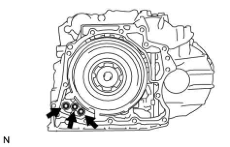
(h) Using a screwdriver, remove the 2 oil seal rings from the rear transaxle cover sub-assembly.

Text in Illustration

(i) Remove the thrust needle roller bearing and thrust needle roller race from the rear transaxle cover sub-assembly.
(j) Using a "TORX" wrench (T30), remove the 2 "TORX" screws and rear transaxle cover plate from the rear transaxle cover sub-assembly.

(k) Using SST, remove the needle roller bearing from the rear transaxle cover sub-assembly.
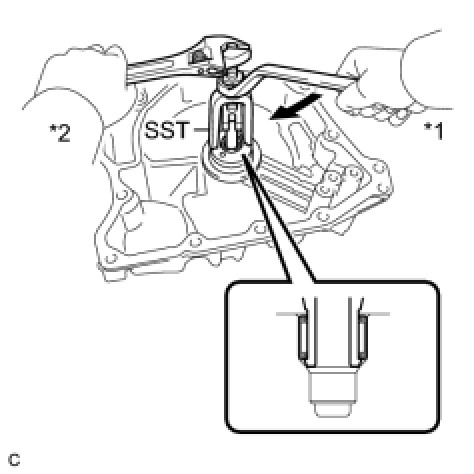
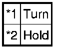
Text in Illustration
SST : 09319-60020
14. REMOVE DIRECT MULTIPLE DISC CLUTCH ASSEMBLY
(a) Remove the direct multiple disc clutch assembly from the transaxle case.

Text in Illustration
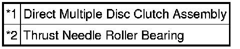
(b) Remove the thrust needle roller bearing from the direct multiple disc clutch assembly.
15. REMOVE DIRECT MULTIPLE DISC CLUTCH SNAP RING
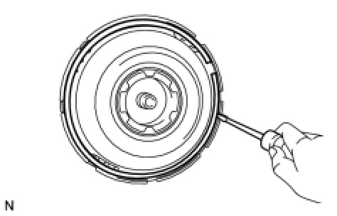
(a) Using a screwdriver, remove the snap ring from the direct multiple disc clutch assembly.
(b) Remove the No. 2 direct clutch piston from the direct multiple disc clutch assembly.
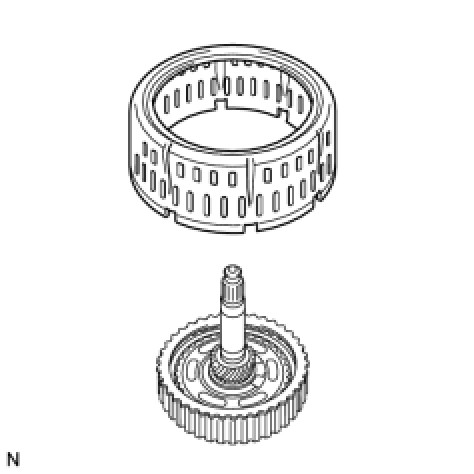
(c) Using a screwdriver, remove the intermediate shaft oil seal from the direct multiple disc clutch assembly.

Text in Illustration

(d) Using a screwdriver, remove the O-ring from the direct multiple disc clutch assembly.
Text in Illustration

16. REMOVE NO. 2 CLUTCH DISC
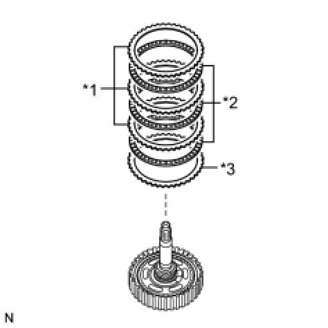
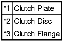
(a) Remove the clutch flange, 3 clutch discs and 3 clutch plates from the direct multiple disc clutch assembly.
Text in Illustration
17. INSPECT NO. 2 CLUTCH DISC Transaxle Unit
18. REMOVE REAR PLANETARY SUN GEAR ASSEMBLY
(a) Using a snap ring expander, remove the snap ring from the direct multiple disc clutch assembly.

(b) Remove the rear planetary sun gear assembly from the direct multiple disc clutch assembly.

(c) Remove the thrust needle roller bearing and thrust needle roller race from the direct multiple disc clutch assembly.
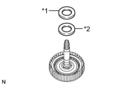
Text in Illustration

19. INSPECT REAR PLANETARY SUN GEAR ASSEMBLY Transaxle Unit
20. REMOVE NO. 1 CLUTCH DISC
(a) Using 2 screwdrivers, remove the 2 snap rings from the direct multiple disc clutch assembly.
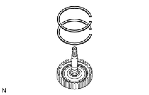
(b) Remove the clutch flange, 4 clutch discs and 4 clutch plates from the direct multiple disc clutch assembly.

Text in Illustration

Factory Service Tools
Use the Manual With the Right Hardware
Pair factory procedures with proven DIY tools so the instructions are easier to execute.
Disclosure: Verified tool recommendations may earn an affiliate commission at no cost to you.
When to See a Mechanic
Stop DIY work and contact a certified mechanic immediately if any of the following apply:
- • You smell fuel, burning insulation, or see smoke.
- • Brakes feel soft, pull hard to one side, or make grinding noises.
- • The engine overheats, stalls repeatedly, or misfires under load.
- • You are missing required tools, torque specs, or safe lifting equipment.
- • You are not confident in the next step or safety outcome.
Rather have a pro handle this?
A certified mobile mechanic comes to your home or office. They bring the tools, you stay comfortable. No tow truck, no waiting room, no surprises.
Comes to youSame-day available12-month warranty
Get a Free QuoteNo obligation. See pricing before you book.