
Safety Warning
DIY auto repair can cause serious injury, fire, or vehicle damage. These guides are for informational purposes only. Always follow OEM torque specs, wear PPE, and consult a certified mechanic if you are unsure. You are solely responsible for your safety.
2012 Toyota Venza FWD V6-3.5L (2GR-FE)FACTORY OEM SERVICE PROCEDURE
Smart Key System (for Start Function)
THEFT DETERRENT / KEYLESS ENTRY: SMART KEY SYSTEM (for Start Function): Engine does not Start
- Engine does not Start
DESCRIPTION
1. ENGINE START SYSTEM FUNCTION
(a) If the engine switch is pressed with the shift lever in P or N and the brake pedal depressed, the power management control ECU determines that this is an engine start request.
(b) The certification ECU (smart key ECU assembly) and other ECUs perform key verification via LIN communication.
(c) The power management control ECU activates the ACC relay.
(d) The power management control ECU activates the IG1 and IG2 relays.
(e) The certification ECU (smart key ECU assembly) outputs a steering UNLOCK signal. The signal is sent to the power management control ECU via the steering lock ECU.
(f) The power management control ECU activates the starter relay.
HINT
When the power management ECU operates the starter relay, it performs cranking holding control.
(g) The power management control ECU deactivates the ACC relay until the power management control ECU detects an engine start.
HINT
Whether the engine has started is judged based on the engine speed signals sent from the ECM.

WIRING DIAGRAM
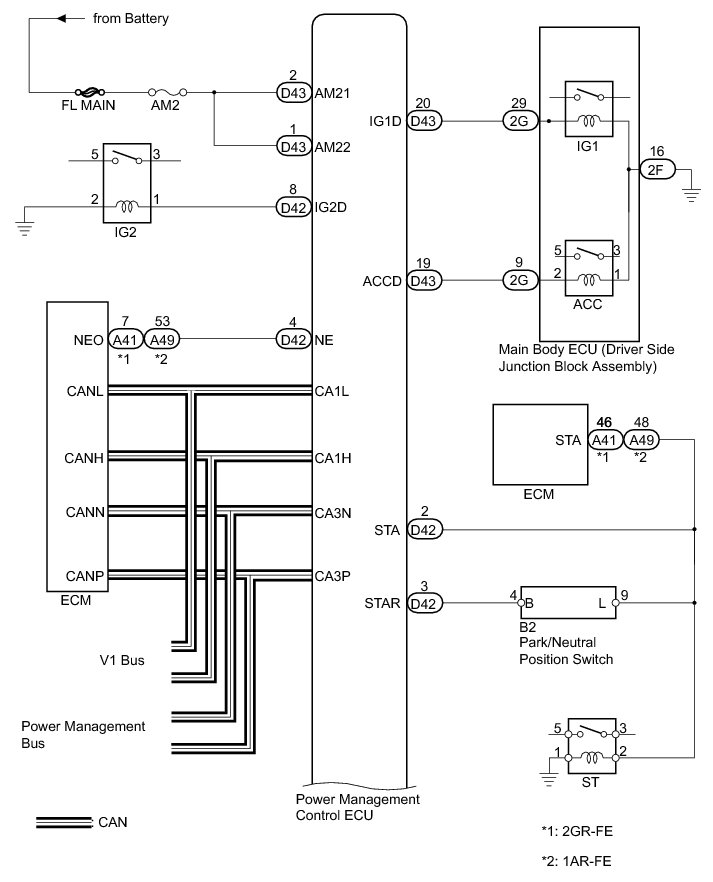

INSPECTION PROCEDURE
1. EMERGENCY ENGINE START CONTROL
(a) If there is a malfunction in the stop light switch or STOP fuse, their signals may not be correctly transmitted to the power management control ECU. This may result in the engine not starting even if the engine switch is pressed while the brake pedal is depressed and the shift lever is in P.
To activate the starter:
(1) Turn the engine switch from off to on (ACC).
(2) Press and hold the engine switch for 15 seconds.
HINT
After the certification ECU (smart key ECU assembly), steering lock ECU, and/or ECM are/is replaced, perform the registration procedure for the engine immobiliser system Engine Immobilizer System (w/ Smart Key System).
PROCEDURE
1. CHECK IF ENGINE STARTS
(a) Place the electrical key on the driver seat.
(b) Move the shift lever to P.
(c) Depress the brake pedal.
(d) Check that the engine switch indicator light is green. Then press the engine switch to check if the engine starts.
OK:
Engine can be started.
NG -- CHECK FOR DTC
OK -- END (ENGINE START PERMISSION CONDITIONS WERE NOT SATISFIED)
2. CHECK FOR DTC
(a) Connect the Techstream to the DLC3.
(b) Turn the engine switch on (IG).
(c) Turn the Techstream on.
(d) Enter the following menus: Body Electrical / each ECU / Trouble Code.
(e) Check for DTCs.
OK:
DTC is not output.
NG -- GO TO DIAGNOSTIC TROUBLE CODE CHART
OK -- Continue to next step.
3. READ VALUE USING TECHSTREAM
(a) Enter the following menus: Body Electrical / Smart key / Data List.
(b) Read the Data List according to the display on the Techstream.
Smart Key

OK:
OK (No malfunction) appears on the screen.
NG -- GO TO STEERING LOCK SYSTEM B2782
OK -- Continue to next step.
4. CHECK POWER SOURCE CONDITION
(a) Check if the power source mode changes.
(1) When the key is inside the vehicle and the shift lever is in P, check that the power source mode changes.
Result:

B -- GO TO OTHER FLOW CHART (Power Source Mode does not Change to ON (IG and ACC)) Power Source Mode does not Change to ON (IG and ACC)
C -- GO TO OTHER FLOW CHART (Power Source Mode does not Change to ON (IG)) Power Source Mode does not Change to ON (IG)
D -- GO TO OTHER FLOW CHART (Power Source Mode does not Change to ON (ACC)) Power Source Mode does not Change to ON (ACC)
A -- Continue to next step.
5. CHECK CRANKING FUNCTION
(a) Check the engine cranking function.
(1) When there is fuel in the fuel tank, the key is inside the vehicle, and the shift lever is in P, check that depressing the brake pedal and pressing the engine switch cranks the engine.
Result:

B -- GO TO SFI SYSTEM (for 2GR-FE) Symptom Related Diagnostic Procedures
C -- GO TO SFI SYSTEM (for 1AR-FE) Symptom Related Diagnostic Procedures
A -- Continue to next step.
6. INSPECT PARK/NEUTRAL POSITION SWITCH ASSEMBLY
(a) Disconnect the B2 connector.

(b) Measure the resistance according to the value(s) in the table below.
Standard Resistance:

Text in Illustration

NG -- REPAIR OR REPLACE HARNESS OR CONNECTOR OR ST RELAY OR PARK/NEUTRAL POSITION SWITCH
OK -- Continue to next step.
7. INSPECT STARTER RELAY ASSEMBLY
(a) Remove the ST relay from the engine room relay block.
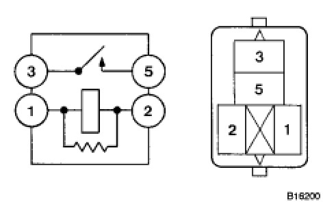
(b) Measure the resistance according to the value(s) in the table below.
Standard Resistance:

NG -- REPAIR OR REPLACE HARNESS OR CONNECTOR OR ST RELAY OR PARK/NEUTRAL POSITION SWITCH
OK -- Continue to next step.
8. CHECK HARNESS AND CONNECTOR (POWER MANAGEMENT CONTROL ECU - BODY GROUND)
(a) Disconnect the D42 connector from the power management control ECU.

(b) The shift lever is in P or N.
(c) Measure the resistance according to the value(s) in the table below.
Standard Resistance:

Text in Illustration

NG -- REPAIR OR REPLACE HARNESS OR CONNECTOR OR ST RELAY OR PARK/NEUTRAL POSITION SWITCH
OK -- Continue to next step.
9. READ VALUE USING TECHSTREAM (STOP LIGHT SWITCH ASSEMBLY)
(a) Enter the following menus: Body Electrical / Power Source Control / Data List.
(b) Read the Data List according to the display on the Techstream.
Power Source Control

OK:
ON (brake pedal depressed) and OFF (brake pedal released) appear on the screen.
NG -- INSPECT STOP LIGHT SWITCH ASSEMBLY
OK -- Continue to next step.
10. READ VALUE USING TECHSTREAM (STEERING UNLOCK SWITCH)
(a) Enter the following menus: Body Electrical / Power Source Control / Date List.
(b) Read the Data List according to the display on the Techstream.
Power Source Control

OK:
ON (steering is unlocked) and OFF (steering is unlocked) appear on the screen.
NG -- CHECK HARNESS AND CONNECTOR (POWER MANAGEMENT CONTROL ECU - STEERING LOCK ECU)
OK -- Continue to next step.
11. CHECK STEERING LOCK
(a) Turn the engine switch from off to on (ACC) and check that the steering lock moves to the unlocked position when the engine switch is on (ACC).
OK:
Lock moves to unlocked position.
NG -- GO TO STEERING LOCK SYSTEM Symptom Related Diagnostic Procedures
OK -- Continue to next step.
12. READ VALUE USING TECHSTREAM (L CODE)
(a) Enter the following menus: Body Electrical / Smart Key / Data List.
(b) Read the Data List according to the display on the Techstream.
Smart Key

OK:
OK appear on the screen.
NG -- GO TO ENGINE IMMOBILISER SYSTEM How To Proceed With Troubleshooting
OK -- Continue to next step.
13. READ VALUE USING TECHSTREAM (ENGINE START REQUEST)
(a) Enter the following menus: Body Electrical / Smart key / Data List.
(b) Read the Data List according to the display on the Techstream.
Smart Key

OK:
OK appear on the screen.
NG -- REPLACE CERTIFICATION ECU (SMART KEY ECU ASSEMBLY)
OK -- Continue to next step.
14. READ VALUE USING TECHSTREAM (S CODE)
(a) Enter the following menus: Body Electrical / Smart key / Data List.
(b) Read the Data List according to the display on the Techstream.
Smart Key

OK:
OK (S code certification result normal) appears on the screen.
NG -- GO TO ENGINE IMMOBILISER SYSTEM How To Proceed With Troubleshooting
OK -- Continue to next step.
15. READ VALUE USING TECHSTREAM (STARTER REQUEST SIGNAL)
(a) Enter the following menu: Body Electrical / Power Source Control / Data List.
(b) Read the Data List according to the value(s) in the table below.
Power Source Control

Result:

B -- GO TO SFI SYSTEM (for 2GR-FE) Symptom Related Diagnostic Procedures
C -- GO TO SFI SYSTEM (for 1AR-FE) Symptom Related Diagnostic Procedures
A -- REPLACE POWER MANAGEMENT CONTROL ECU Removal
16. INSPECT STOP LIGHT SWITCH ASSEMBLY B2284
NG -- REPLACE STOP LIGHT SWITCH ASSEMBLY Removal
OK -- Continue to next step.
17. CHECK HARNESS AND CONNECTOR (STOP LIGHT SWITCH ASSEMBLY - POWER MANAGEMENT CONTROL ECU)
(a) Disconnect the D42 connector from the power management control ECU.

(b) Measure the resistance according to the value(s) in the table below.
Standard Resistance:

Text in Illustration

(c) Reconnect the D42 connector to the power management control ECU.
(d) Measure the voltage according to the value(s) in the table below.
Standard Voltage:

NG -- REPAIR OR REPLACE HARNESS OR CONNECTOR
OK -- REPLACE POWER MANAGEMENT CONTROL ECU Removal
18. CHECK HARNESS AND CONNECTOR (POWER MANAGEMENT CONTROL ECU - STEERING LOCK ECU) B2285
NG -- REPAIR OR REPLACE HARNESS OR CONNECTOR
OK -- Continue to next step.
19. INSPECT STEERING LOCK ACTUATOR ASSEMBLY
(a) Reconnect the D17 connector to the steering lock actuator assembly (steering lock ECU).
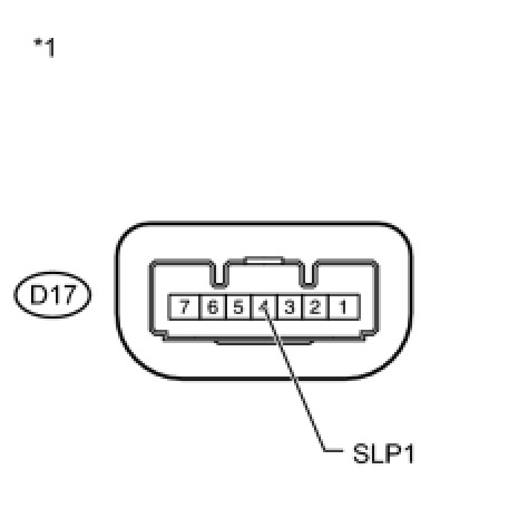
(b) Measure the resistance according to the value(s) in the table below.
Standard Resistance:

Text in Illustration

NG -- REPLACE STEERING LOCK ACTUATOR ASSEMBLY Disassembly
OK -- REPLACE POWER MANAGEMENT CONTROL ECU Removal
20. REPAIR OR REPLACE HARNESS OR CONNECTOR OR ST RELAY OR PARK/NEUTRAL POSITION SWITCH
(a) Replace with a new or normally functioning part. Repair or replace any damaged wire harness or connector.
NEXT -- Continue to next step.
21. READ VALUE USING TECHSTREAM (STARTER REQUEST SIGNAL)
(a) Enter the following menus: Body Electrical / Power Source Control / Data List.
(b) Read the Data List according to the display on the Techstream.
Power Source Control

NOTICE:
Check that the engine switch indicator is illuminated in green and push the engine switch.
OK:
ON (ST relay on) and OFF (ST relay off) appear on the screen.
NG -- REPLACE POWER MANAGEMENT CONTROL ECU Removal
OK -- Continue to next step.
22. CHECK IF ENGINE STARTS
(a) Place the electrical key on the driver seat.
(b) Move the shift lever to P.
(c) Depress the brake pedal.
(d) Check that the engine switch indicator light is green. Then press the engine switch to check if the engine starts.
OK:
Engine can be started.
NG -- CHECK HARNESS AND CONNECTOR (MALFUNCTION IN RELAY CONTACT SIDE CIRCUIT)
OK -- END
Factory Service Tools
Use the Manual With the Right Hardware
Pair factory procedures with proven DIY tools so the instructions are easier to execute.
Disclosure: Verified tool recommendations may earn an affiliate commission at no cost to you.
When to See a Mechanic
Stop DIY work and contact a certified mechanic immediately if any of the following apply:
- • You smell fuel, burning insulation, or see smoke.
- • Brakes feel soft, pull hard to one side, or make grinding noises.
- • The engine overheats, stalls repeatedly, or misfires under load.
- • You are missing required tools, torque specs, or safe lifting equipment.
- • You are not confident in the next step or safety outcome.
Rather have a pro handle this?
A certified mobile mechanic comes to your home or office. They bring the tools, you stay comfortable. No tow truck, no waiting room, no surprises.
Comes to youSame-day available12-month warranty
Get a Free QuoteNo obligation. See pricing before you book.