
Safety Warning
DIY auto repair can cause serious injury, fire, or vehicle damage. These guides are for informational purposes only. Always follow OEM torque specs, wear PPE, and consult a certified mechanic if you are unsure. You are solely responsible for your safety.
2012 Toyota Matrix FWD L4-2.4L (2AZ-FE)FACTORY OEM SERVICE PROCEDURE
Pinout Values and Diagnostic Parameters
2AZ-FE ENGINE CONTROL: SFI SYSTEM: TERMINALS OF ECM
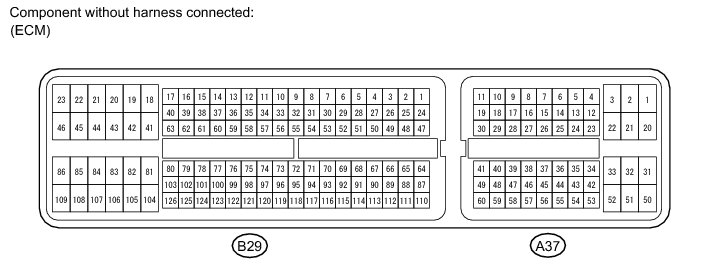
HINT
The standard normal voltage between each pair of ECM terminals is shown in the table below. The appropriate conditions for checking each pair of terminals are also indicated. The result of checks should be compared with the standard normal voltage for that pair of terminals, displayed in the Specified Condition column. The illustration above can be used as a reference to identify the ECM terminal locations.
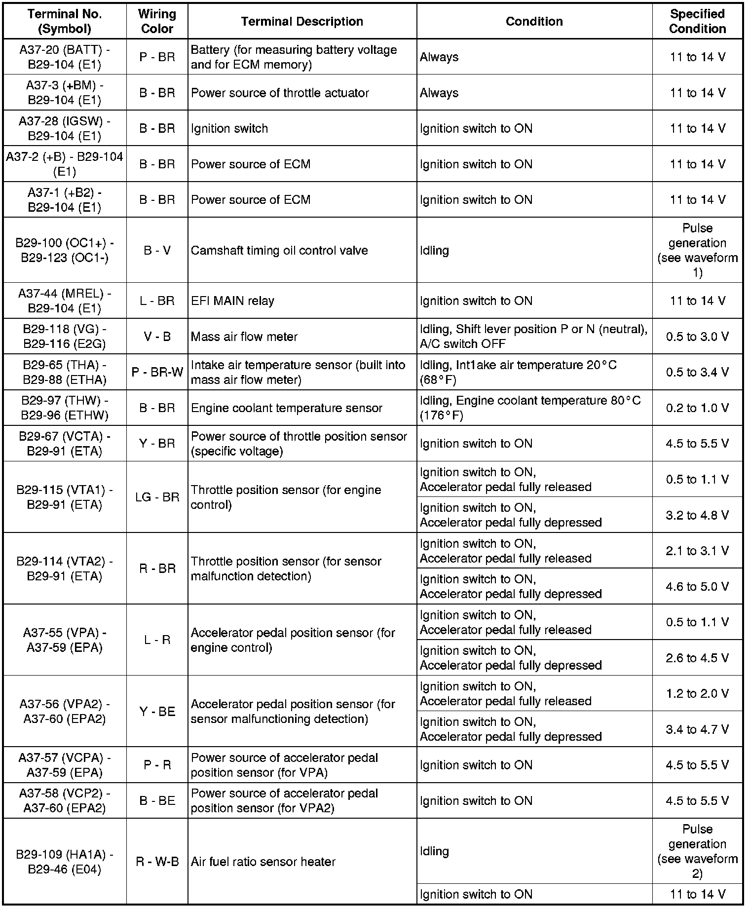

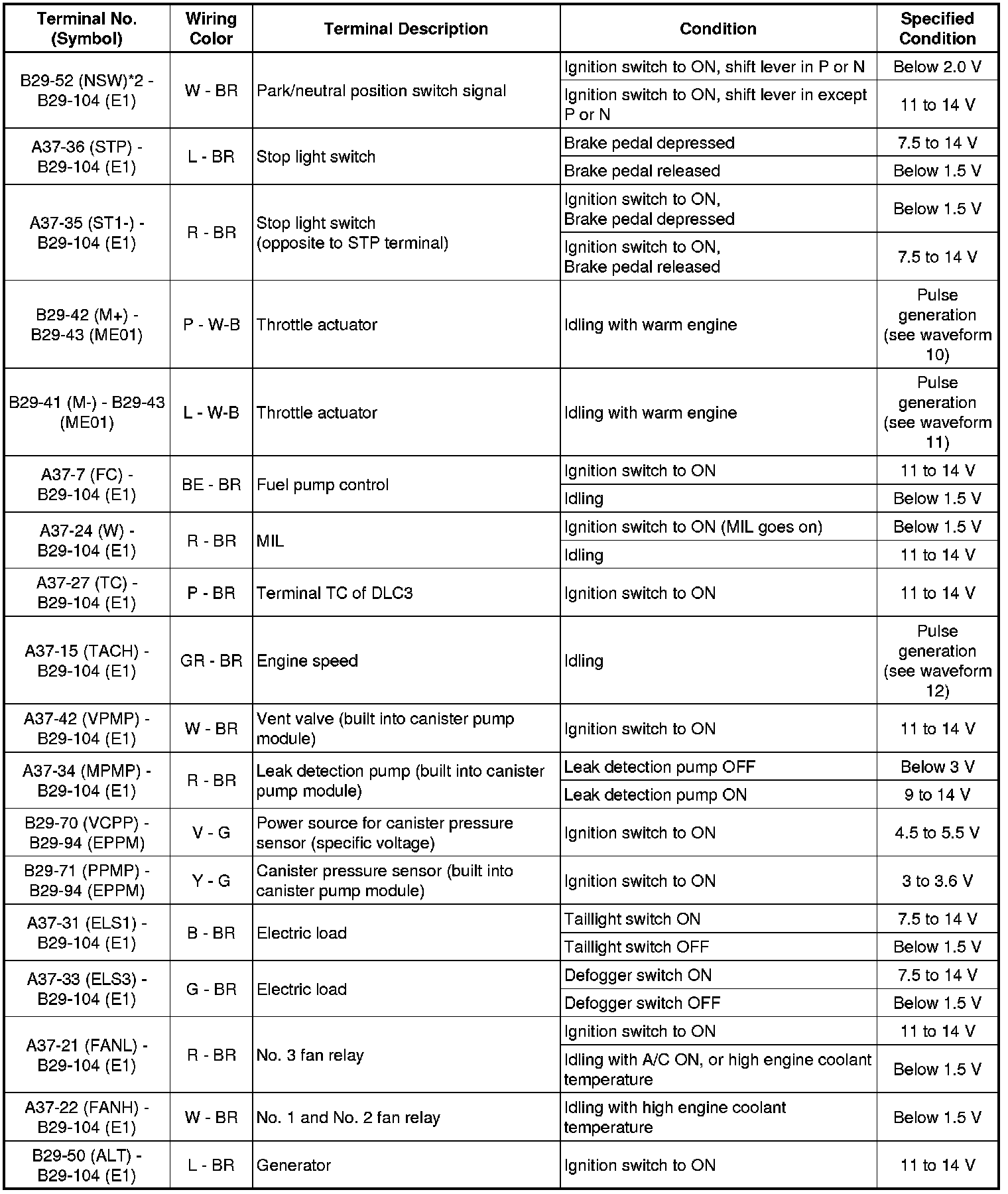
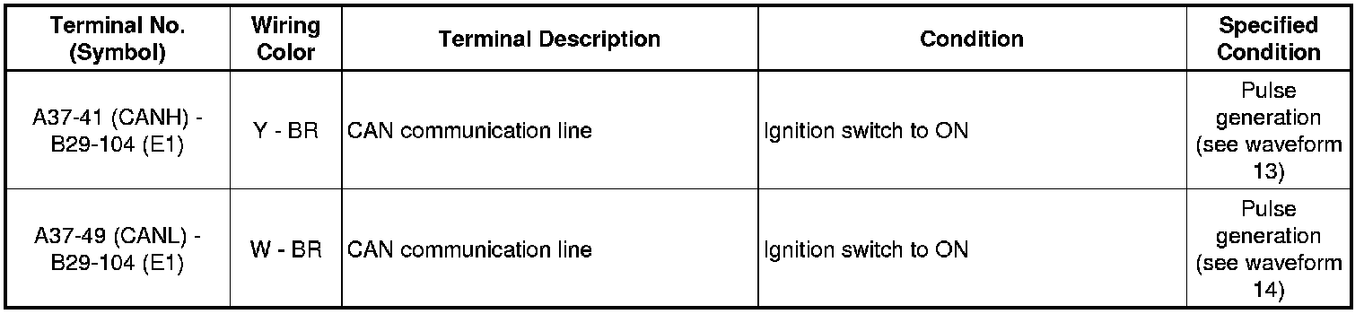
HINT
*1: The ECM terminal voltage is constant regardless of the output voltage from the sensor.
*2: Automatic Transaxle
*3: 2WD
*4: 4WD
1. WAVEFORM 1
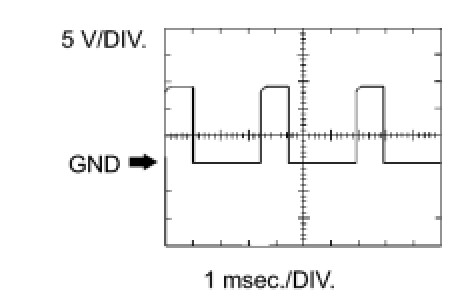
Camshaft Timing Oil Control Valve
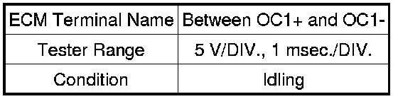
2. WAVEFORM 2

Air Fuel Ratio Sensor (Sensor 1) Heater
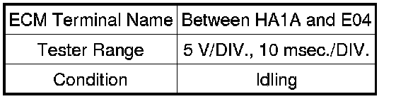
HINT
The wavelength varies in accordance with the engine operating condition.
3. WAVEFORM 3
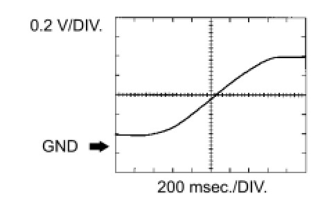
Heated Oxygen Sensor (Sensor 2)

HINT
In Data List, item O2S B1S2 shows the ECM input values from the heated oxygen sensor.
4. WAVEFORM 4

Injector No. 1 (to No. 4) Injection Signal
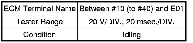
HINT
The wavelength becomes shorter as the engine speed increases.
5. WAVEFORM 5
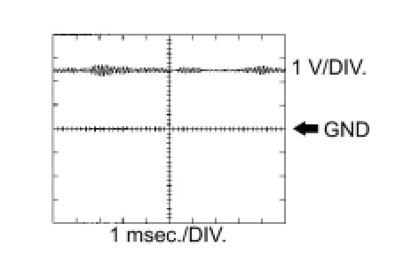
Knock Sensor

HINT
* The wavelength becomes shorter as the engine speed increases.
* The waveforms and amplitudes displayed differ slightly depending on the vehicle.
6. WAVEFORM 6

Crankshaft Position Sensor and Camshaft Position Sensor
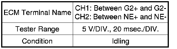
HINT
The wavelength becomes shorter as the engine speed increases.
7. WAVEFORM 7
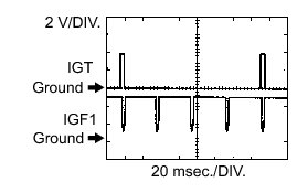
Igniter IGT Signal (from ECM to igniter) and Igniter IGF Signal (from igniter to ECM)

HINT
The wavelength becomes shorter as the engine speed increases.
8. WAVEFORM 8

Purge VSV

HINT
If the waveform is not similar to the illustration, check the waveform again after idling for 10 minutes or more.
9. WAVEFORM 9

Vehicle Speed Signal

HINT
The wavelength becomes shorter as the vehicle speed increases.
10. WAVEFORM 10

Throttle Actuator Positive Terminal

HINT
The duty ratio varies depending on the throttle actuator operation.
11. WAVEFORM 11

Throttle Actuator Negative Terminal

HINT
The duty ratio varies depending on the throttle actuator operation.
12. WAVEFORM 12

Engine Speed Signal
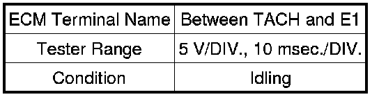
HINT
The wavelength becomes shorter as the engine speed increases.
13. WAVEFORM 13

CAN Communication Signal (Reference)
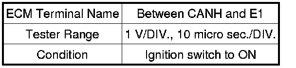
HINT
The waveform varies depending on the CAN communication signal.
14. WAVEFORM 14
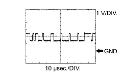
CAN Communication Signal (Reference)
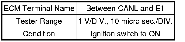
HINT
The waveform varies depending on the CAN communication signal.
Factory Service Tools
Use the Manual With the Right Hardware
Pair factory procedures with proven DIY tools so the instructions are easier to execute.
Disclosure: Verified tool recommendations may earn an affiliate commission at no cost to you.
When to See a Mechanic
Stop DIY work and contact a certified mechanic immediately if any of the following apply:
- • You smell fuel, burning insulation, or see smoke.
- • Brakes feel soft, pull hard to one side, or make grinding noises.
- • The engine overheats, stalls repeatedly, or misfires under load.
- • You are missing required tools, torque specs, or safe lifting equipment.
- • You are not confident in the next step or safety outcome.