
Safety Warning
DIY auto repair can cause serious injury, fire, or vehicle damage. These guides are for informational purposes only. Always follow OEM torque specs, wear PPE, and consult a certified mechanic if you are unsure. You are solely responsible for your safety.
2010 Toyota Matrix FWD L4-2.4L (2AZ-FE)FACTORY OEM SERVICE PROCEDURE
Disassembly
E351 MANUAL TRANSMISSION / TRANSAXLE: INPUT SHAFT: DISASSEMBLY
1. REMOVE 4TH GEAR
(a) Hold the input shaft assembly in a vise using aluminum plates.
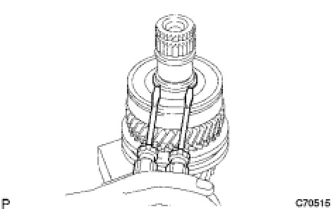
(b) Using 2 screwdrivers and a hammer, remove the input shaft rear bearing shaft snap ring from the input shaft.
HINT
Use a piece of cloth to keep the snap ring from flying.
(c) Using SST and a press, remove the input shaft rear bearing and 4th gear.
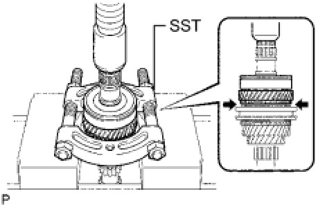
SST : 09950-00020
NOTICE:
Do not overtighten SST.
2. REMOVE 4TH GEAR NEEDLE ROLLER BEARING
(a) Remove the 4th gear needle roller bearing from the input shaft.

3. REMOVE NO. 4 SYNCHRONIZER RING
(a) Remove the No. 4 synchronizer ring from the No. 2 transmission clutch hub.

4. REMOVE 4TH GEAR BEARING SPACER
(a) Remove the 4th gear bearing spacer from the No. 2 transmission clutch hub.

5. REMOVE 3RD GEAR
(a) Using 2 screwdrivers and a hammer, remove the No. 2 clutch hub setting shaft snap ring from the input shaft.

HINT
Use a piece of cloth to keep the snap ring from flying.
(b) Using SST and a press, remove the No. 2 transmission clutch hub and 3rd gear from the input shaft.
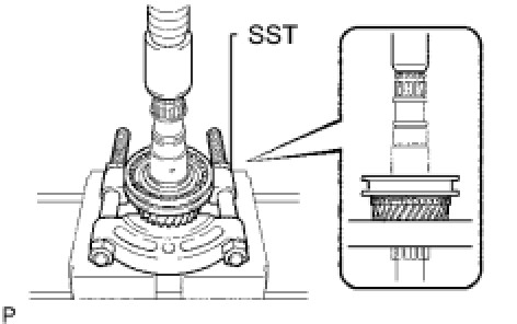
SST : 09950-00020
NOTICE:
Do not overtighten SST.
6. REMOVE 3RD GEAR NEEDLE ROLLER BEARING
(a) Remove the 3rd gear needle roller bearing from the input shaft.

7. REMOVE NO. 3 SYNCHRONIZER RING
(a) Remove the No. 3 synchronizer ring from the 3rd gear.
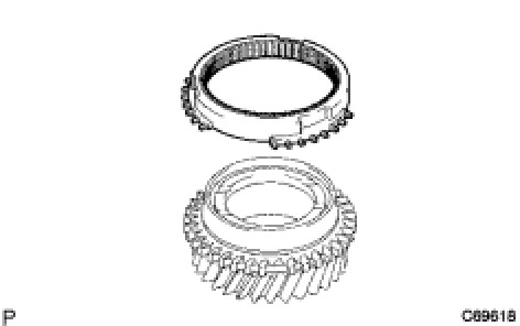
8. REMOVE NO. 2 TRANSMISSION HUB SLEEVE
(a) Remove the No. 2 transmission hub sleeve, 3 No. 2 synchromesh shifting keys, and 3 No. 2 synchromesh shifting key springs from the No. 2 transmission clutch hub.

HINT
Use a piece of cloth to keep the shifting keys and shifting key springs from flying.
9. REMOVE INPUT SHAFT FRONT BEARING
(a) Using SST and a press, remove the input shaft front bearing (inner race) from the input shaft.
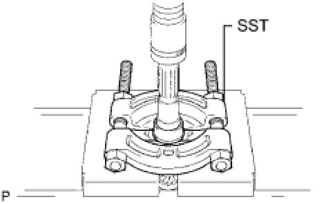
SST : 09950-00020
NOTICE:
Do not overtighten SST.
Factory Service Tools
Use the Manual With the Right Hardware
Pair factory procedures with proven DIY tools so the instructions are easier to execute.
Disclosure: Verified tool recommendations may earn an affiliate commission at no cost to you.
When to See a Mechanic
Stop DIY work and contact a certified mechanic immediately if any of the following apply:
- • You smell fuel, burning insulation, or see smoke.
- • Brakes feel soft, pull hard to one side, or make grinding noises.
- • The engine overheats, stalls repeatedly, or misfires under load.
- • You are missing required tools, torque specs, or safe lifting equipment.
- • You are not confident in the next step or safety outcome.
Rather have a pro handle this?
A certified mobile mechanic comes to your home or office. They bring the tools, you stay comfortable. No tow truck, no waiting room, no surprises.
Comes to youSame-day available12-month warranty
Get a Free QuoteNo obligation. See pricing before you book.