
Safety Warning
DIY auto repair can cause serious injury, fire, or vehicle damage. These guides are for informational purposes only. Always follow OEM torque specs, wear PPE, and consult a certified mechanic if you are unsure. You are solely responsible for your safety.
2006 Toyota Sienna AWD V6-3.3L (3MZ-FE)FACTORY OEM SERVICE PROCEDURE
Transmission Installation
AUTOMATIC TRANSAXLE ASSEMBLY
INSTALLATION
1. INSTALL TORQUE CONVERTER CLUTCH ASSEMBLY
a. Install the torque converter clutch to the automatic transaxle.
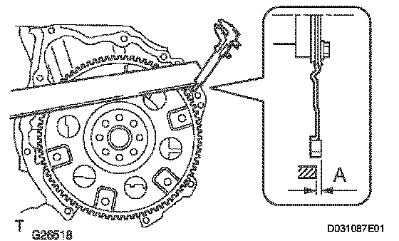
b. Using vernier calipers and a straight edge, measure the dimension A between the transaxle fitting part of the engine and the converter fitting part of the drive plate (*1).
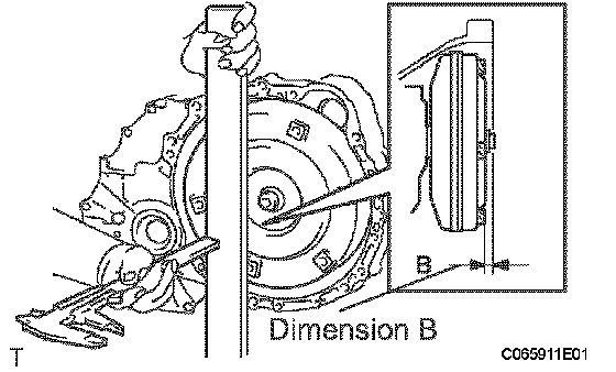
c. Using vernier calipers and a straight edge, measure the dimension B shown in the illustration and check that B is greater than A (measured in step (*1))
Standard: A + 1 mm (0.03937 inch) or more
NOTICE: Remember to minus the thickness of the straight edge.
2. INSTALL TRANSFER ASSEMBLY
3. INSTALL AUTOMATIC TRANSAXLE W/TRANSFER
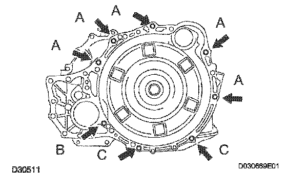
a. Install the automatic transaxle w/transfer with the 8 bolts to the engine.
Torque:
Bolt A: 64 Nm (650 kg-cm, 47 ft. lbs.)
Bolt B: 46 Nm (470 kg-cm, 34 ft. lbs.)
Bolt C: 37 Nm (377 kg-cm, 27 ft. lbs.)
b. Apply a few drops of adhesive to each of 2 threads on the tip of the 6 torque converter clutch mounting bolts.
Adhesive: Part No.08833-00070, THREE BOND 1324 or equivalent
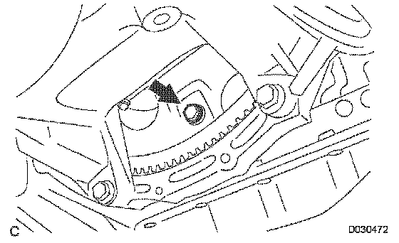
c. Install the 6 torque converter clutch mounting bolts.
Torque: 48 Nm (489 kg-cm, 35 ft. lbs.)
NOTICE: First install the black colored bolt, and then the remaining 5 bolts.
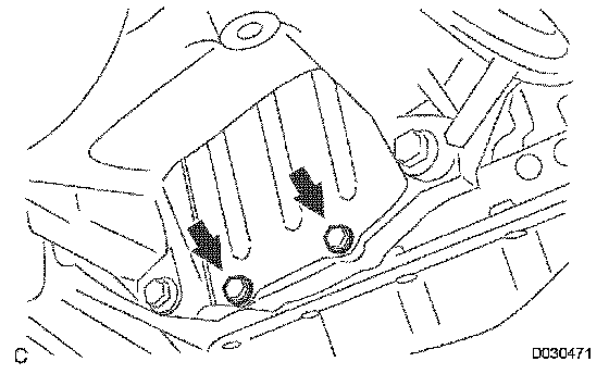
d. Install the flywheel housing under cover to the automatic transaxle with the 2 bolt.
Torque: 7.8 Nm (80 kg-cm, 69 inch lbs.) inch lbs.)
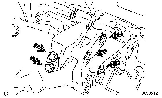
4. INSTALL TRANSFER STIFFENER PLATE RH
a. Install the transfer stiffener plate RH with 5 bolts to the transfer and engine mounting bracket RR.
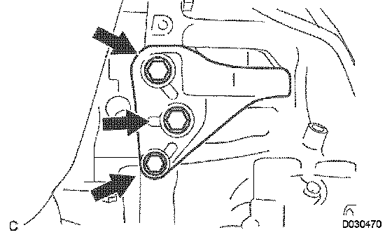
5. INSTALL ENGINE MOUNTING BRACKET FRONT
a. Install the engine mounting bracket front to the automatic transaxle with the 3 bolts.
Torque: 64 Nm (653 kg-cm. 47 ft. lbs.)
6. INSTALL TRANSMISSION OIL FILLER TUBE SUB ASSEMBLY
a. Coat a new O-ring with ATF, and install it to the transmission oil filler tube sub-assembly.
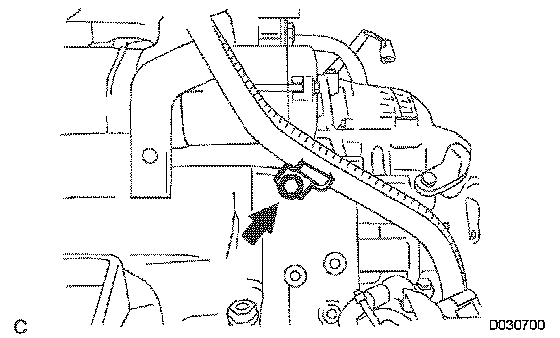
b. Install the transmission oil filler tube sub-assembly and bolt to the automatic transaxle.
Torque: 5.5 Nm (56 kg-cm, 49 inch lbs.)
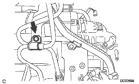
c. Connect the 2 clamps to the oil filler tube.
d. Install the ATF level gauge.
7. INSTALL OIL COOLER INLET TUBE NO.1
a. Temporarily install the oil cooler outlet tube No.1.
b. Temporarily install the oil cooler inlet tube No.1.
c. Install the oil cooler tube clamp and bolt.
Torque: 5.5 Nm (56 kg-cm, 49 inch lbs.)
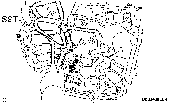
d. Using SST and a wrench, tighten the oil cooler inlet tube No.1.
SST 09023-12701
Torque: 34 Nm (347 kg-cm, 25 ft. lbs.)
8. INSTALL OIL COOLER OUTLET TUBE NO.1
a. Using SST and a wrench, tighten the oil cooler outlet tube No.1.
SST 09023-12701
Torque: 34 Nm (347 kg-cm, 25 ft. lbs.)
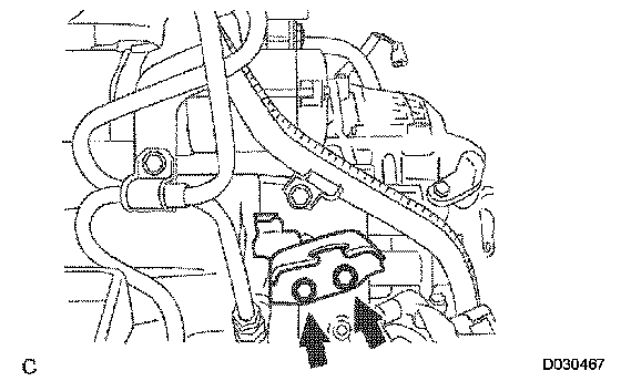
9. INSTALL TRANSMISSION CONTROL CABLE BRACKET NO.1
a. Install the control cable bracket No.1 with the 2 bolts.
Torque: 12 Nm (122 kg-cm, 9 ft. lbs.)
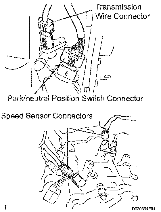
10. CONNECT CONNECTORS
a. Connect the transmission wire connector.
b. Connect the park/neutral position switch connector.
c. Connect the 2 speed sensor connectors.
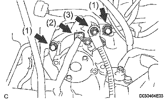
11. INSTALL STARTER ASSEMBLY
a. Install the starter assembly with the 2 bolts (1).
Torque: 37 Nm (377 kg-cm, 27 ft. lbs.)
b. Connect the connector (2).
c. Connect the starter wire with the nut (3).
Torque: 9.8 Nm (100 kg-cm, 87 inch lbs.)

12. CONNECT WIRE HARNESS
a. Connect the wire harness with the bolt.
Torque: 13 Nm (133 kg-cm, 10 ft. lbs.)
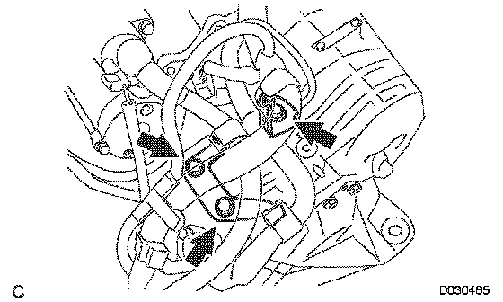
13. INSTALL WIRE HARNESS CLAMP
a. Install the 2 clamps and 3 bolts.
Torque: 8.4 Nm (86 kg-cm, 74 inch lbs.)
b. Connect the wire harnesses to the clamps.
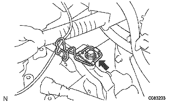
14. INSTALL TRANSMISSION CONTROL CABLE CLAMP
a. Install the transmission control cable clamp with the bolt.
Torque: 12 Nm (122 kg-cm, 9 ft. lbs.)
15. INSTALL FRONT DRIVE SHAFT ASSEMBLY LH
16. INSTALL FRONT DRIVE SHAFT ASSEMBLY RH
17. INSTALL ENGINE ASSEMBLY WITH TRANSAXLE
18. RESET MEMORY
INSTALLATION
1. INSTALL TORQUE CONVERTER CLUTCH ASSEMBLY
a. Install the torque converter clutch to the automatic transaxle.
b. Using vernier calipers and a straight edge, measure the dimension A between the transaxle fitting part of the engine and the converter fitting part of the drive plate (*1).
c. Using vernier calipers and a straight edge, measure the dimension B shown in the illustration and check that B is greater than A (measured in step (*1))
Standard: A + 1 mm (0.03937 inch) or more
NOTICE: Remember to minus the thickness of the straight edge.
2. INSTALL TRANSFER ASSEMBLY
3. INSTALL AUTOMATIC TRANSAXLE W/TRANSFER
a. Install the automatic transaxle w/transfer with the 8 bolts to the engine.
Torque:
Bolt A: 64 Nm (650 kg-cm, 47 ft. lbs.)
Bolt B: 46 Nm (470 kg-cm, 34 ft. lbs.)
Bolt C: 37 Nm (377 kg-cm, 27 ft. lbs.)
b. Apply a few drops of adhesive to each of 2 threads on the tip of the 6 torque converter clutch mounting bolts.
Adhesive: Part No.08833-00070, THREE BOND 1324 or equivalent
c. Install the 6 torque converter clutch mounting bolts.
Torque: 48 Nm (489 kg-cm, 35 ft. lbs.)
NOTICE: First install the black colored bolt, and then the remaining 5 bolts.
d. Install the flywheel housing under cover to the automatic transaxle with the 2 bolt.
Torque: 7.8 Nm (80 kg-cm, 69 inch lbs.) inch lbs.)
4. INSTALL TRANSFER STIFFENER PLATE RH
a. Install the transfer stiffener plate RH with 5 bolts to the transfer and engine mounting bracket RR.
5. INSTALL ENGINE MOUNTING BRACKET FRONT
a. Install the engine mounting bracket front to the automatic transaxle with the 3 bolts.
Torque: 64 Nm (653 kg-cm. 47 ft. lbs.)
6. INSTALL TRANSMISSION OIL FILLER TUBE SUB ASSEMBLY
a. Coat a new O-ring with ATF, and install it to the transmission oil filler tube sub-assembly.
b. Install the transmission oil filler tube sub-assembly and bolt to the automatic transaxle.
Torque: 5.5 Nm (56 kg-cm, 49 inch lbs.)
c. Connect the 2 clamps to the oil filler tube.
d. Install the ATF level gauge.
7. INSTALL OIL COOLER INLET TUBE NO.1
a. Temporarily install the oil cooler outlet tube No.1.
b. Temporarily install the oil cooler inlet tube No.1.
c. Install the oil cooler tube clamp and bolt.
Torque: 5.5 Nm (56 kg-cm, 49 inch lbs.)
d. Using SST and a wrench, tighten the oil cooler inlet tube No.1.
SST 09023-12701
Torque: 34 Nm (347 kg-cm, 25 ft. lbs.)
8. INSTALL OIL COOLER OUTLET TUBE NO.1
a. Using SST and a wrench, tighten the oil cooler outlet tube No.1.
SST 09023-12701
Torque: 34 Nm (347 kg-cm, 25 ft. lbs.)
9. INSTALL TRANSMISSION CONTROL CABLE BRACKET NO.1
a. Install the control cable bracket No.1 with the 2 bolts.
Torque: 12 Nm (122 kg-cm, 9 ft. lbs.)
10. CONNECT CONNECTORS
a. Connect the transmission wire connector.
b. Connect the park/neutral position switch connector.
c. Connect the 2 speed sensor connectors.
11. INSTALL STARTER ASSEMBLY
a. Install the starter assembly with the 2 bolts (1).
Torque: 37 Nm (377 kg-cm, 27 ft. lbs.)
b. Connect the connector (2).
c. Connect the starter wire with the nut (3).
Torque: 9.8 Nm (100 kg-cm, 87 inch lbs.)
12. CONNECT WIRE HARNESS
a. Connect the wire harness with the bolt.
Torque: 13 Nm (133 kg-cm, 10 ft. lbs.)
13. INSTALL WIRE HARNESS CLAMP
a. Install the 2 clamps and 3 bolts.
Torque: 8.4 Nm (86 kg-cm, 74 inch lbs.)
b. Connect the wire harnesses to the clamps.
14. INSTALL TRANSMISSION CONTROL CABLE CLAMP
a. Install the transmission control cable clamp with the bolt.
Torque: 12 Nm (122 kg-cm, 9 ft. lbs.)
15. INSTALL FRONT DRIVE SHAFT ASSEMBLY LH
16. INSTALL FRONT DRIVE SHAFT ASSEMBLY RH
17. INSTALL ENGINE ASSEMBLY WITH TRANSAXLE
18. RESET MEMORY
Factory Service Tools
Use the Manual With the Right Hardware
Pair factory procedures with proven DIY tools so the instructions are easier to execute.
Disclosure: Verified tool recommendations may earn an affiliate commission at no cost to you.
When to See a Mechanic
Stop DIY work and contact a certified mechanic immediately if any of the following apply:
- • You smell fuel, burning insulation, or see smoke.
- • Brakes feel soft, pull hard to one side, or make grinding noises.
- • The engine overheats, stalls repeatedly, or misfires under load.
- • You are missing required tools, torque specs, or safe lifting equipment.
- • You are not confident in the next step or safety outcome.
Rather have a pro handle this?
A certified mobile mechanic comes to your home or office. They bring the tools, you stay comfortable. No tow truck, no waiting room, no surprises.
Comes to youSame-day available12-month warranty
Get a Free QuoteNo obligation. See pricing before you book.