
Safety Warning
DIY auto repair can cause serious injury, fire, or vehicle damage. These guides are for informational purposes only. Always follow OEM torque specs, wear PPE, and consult a certified mechanic if you are unsure. You are solely responsible for your safety.
2006 Toyota Sienna AWD V6-3.3L (3MZ-FE)FACTORY OEM SERVICE PROCEDURE
Removal and Installation
COMPRESSOR AND MAGNETIC CLUTCH
REMOVAL
1. DISCHARGE REFRIGERANT FROM REFRIGERATION SYSTEM
SST 07110-58060 (07117-58080, 07117-58090, 07117-78050, 07117-88060, 07117-88070, 07117-88080)
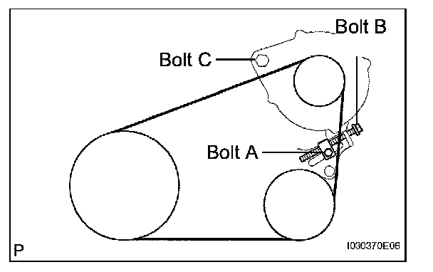
2. REMOVE V (COOLER COMPRESSOR TO CRANKSHAFT PULLEY) BELT NO.1
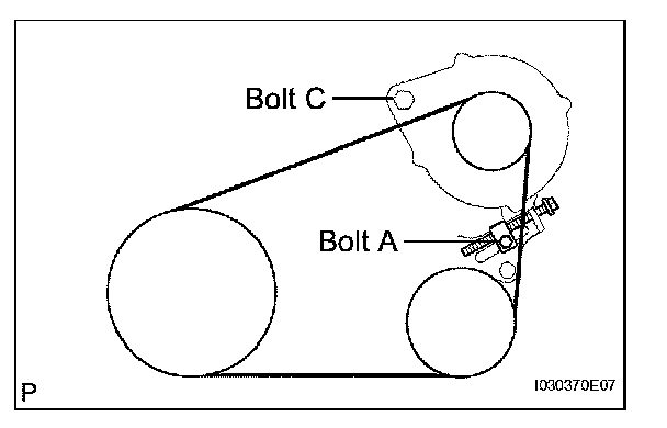
a. Loosen the bolt C.
b. Loosen the bolt A.
c. Loosen the bolt B and remove the V (cooler compressor to crankshaft pulley) belt No.1.
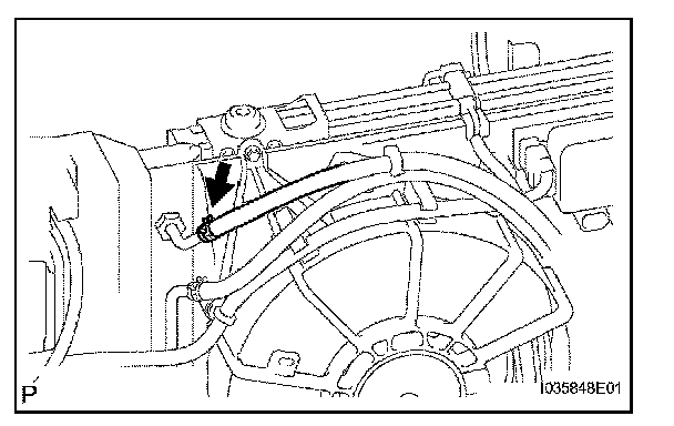
3. DISCONNECT OIL COOLER INLET HOSE NO.1
a. Using pliers, grip the claws of the clip side to disconnect the oil cooler inlet hose No. 1.
4. DISCONNECT OIL COOLER OUTLET HOSE NO.1
HINT: Disconnection of the oil cooler outlet hose No. 1 is the same way as the oil cooler inlet hose No. 1.
5. REMOVE FAN ASSEMBLY WITH MOTOR

a. Release the 3 clamps.
b. Disconnect the connectors.
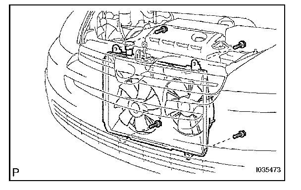
c. Remove the 4 bolts and the fan assembly w/ motor.
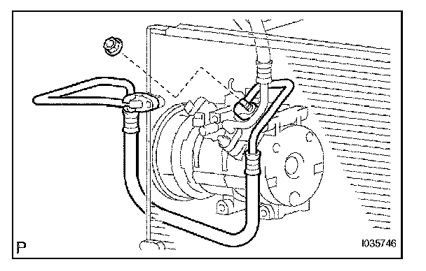
6. DISCONNECT DISCHARGE HOSE SUB-ASSEMBLY
a. Remove the nut and disconnect the discharge hose sub-assembly from the compressor and magnetic clutch.
b. Remove the O-ring from the discharge hose subassembly.
NOTE: Seal the opening of the disconnected parts using vinyl tape to prevent moisture and foreign matters from entering.
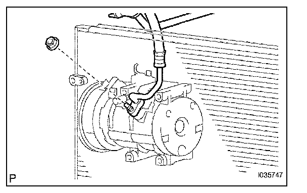
7. DISCONNECT SUCTION HOSE SUB-ASSEMBLY
a. Remove the nut and disconnect the suction hose sub-assembly from the compressor and magnetic clutch.
b. Remove the O-ring from the suction hose subassembly.
NOTE: Seal the opening of the disconnected parts using vinyl tape to prevent moisture and foreign matters from entering.
8. REMOVE COMPRESSOR AND MAGNETIC CLUTCH

a. Disconnect the connector.
b. Release the 2 clamps and wire harness.
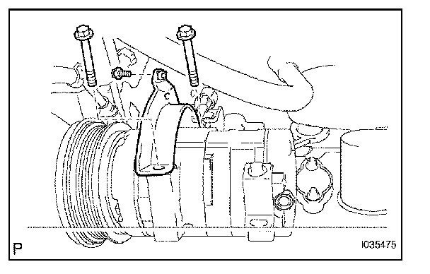
c. Remove the 3 bolts and the cooler compressor bracket.
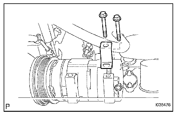
d. Remove the 2 bolts, the stay, and the compressor and magnetic clutch.
INSTALLATION
1. INSTALL COMPRESSOR AND MAGNETIC CLUTCH
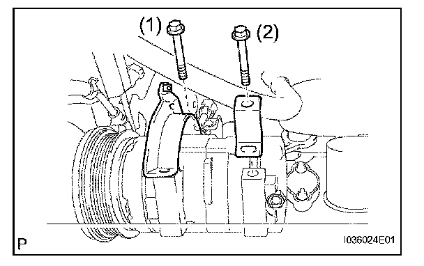
a. Install the compressor, the magnetic clutch, the stay and cooler compressor bracket with the 2 bolts.
Torque: 24 N.m (245 kgf.cm, 18 ft.lbf)
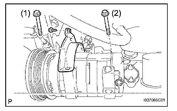
b. Install the 3 bolts.
Torque: 24 N.m (245 kgf.cm, 18 ft.lbf)
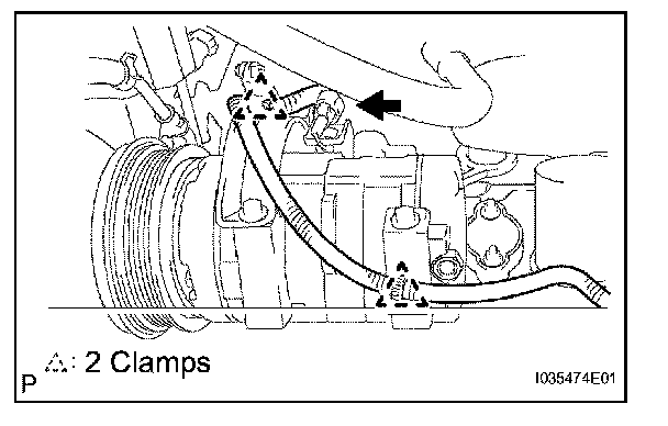
c. Connect the 2 clamps and wire harness.
d. Connect the connector.
2. INSTALL SUCTION HOSE SUB-ASSEMBLY
a. Remove the attached vinyl tape from the hose.
b. Sufficiently apply compressor oil to a new O-ring and the fitting surface of the compressor and magnetic clutch.
Compressor oil: ND-OIL 8 or equivalent
c. Install the O-ring on the suction hose sub-assembly.

d. Install the suction hose sub-assembly on the compressor and magnetic clutch with the nut.
Torque: 5.4 N.m (55 kgf.cm, 48 in.lbf)
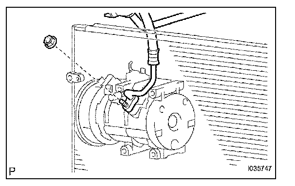
3. INSTALL DISCHARGE HOSE SUB-ASSEMBLY
a. Remove the attached vinyl tape from the hose.
b. Sufficiently apply compressor oil to a new O-ring and the fitting surface of the compressor and magnetic clutch.
Compressor oil: ND-OIL 8 or equivalent
c. Install the O-ring on the discharge hose subassembly.
d. Install the discharge hose sub-assembly on the compressor and magnetic clutch with the nut.
Torque: 5.4 N.m (55 kgf.cm, 48 in.lbf)

4. INSTALL V (COOLER COMPRESSOR TO CRANKSHAFT PULLEY) BELT NO.1
a. Temporarily install the V (cooler compressor to crankshaft pulley) belt No. 1 as illustrated.

5. ADJUST V (COOLER COMPRESSOR TO CRANKSHAFT PULLEY) BELT NO.1
a. Apply drive belt tension by turning the bolt B.
Drive Belt Tension:
New Belt: 165 ± 27 lbf
Used Belt: 88 ± 22 lbf
HINT:
- "New belt" refers to a belt which has been used less than 5 minutes on a running engine.
- "Used belt" refers to a belt which has been used on a running engine for 5 minutes or more.
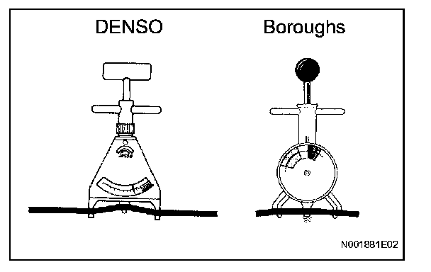
b. Using a belt tension gauge, check the V belt tension.
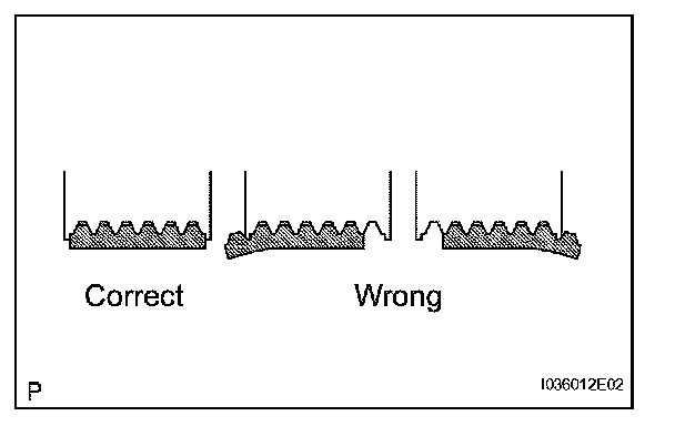
c. Check that the drive fits properly in the ribbed grooves.
6. FULLY TIGHTEN V (COOLER COMPRESSOR TO CRANKSHAFT PULLEY) BELT NO.1
a. Tighten the bolt A.
Torque: 17.5 N.m (178 kgf.cm, 12 ft.lbf)
b. Tighten the bolt C.
Torque: 58 N.m (591 kgf.cm, 43 ft.lbf)
7. CHARGE REFRIGERANT
SST 07110-58060 (07117-58060, 07117-58070, 07117-58080, 07117-58090, 07117-78050, 07117-88060, 07117-88070, 07117-88080)
Specified amount: 780 ± 30 g (27.5 ± 1.06 oz.)
8. WARM UP ENGINE
9. INSPECT REFRIGERANT LEAKAGE
REMOVAL
1. DISCHARGE REFRIGERANT FROM REFRIGERATION SYSTEM
SST 07110-58060 (07117-58080, 07117-58090, 07117-78050, 07117-88060, 07117-88070, 07117-88080)
2. REMOVE V (COOLER COMPRESSOR TO CRANKSHAFT PULLEY) BELT NO.1
a. Loosen the bolt C.
b. Loosen the bolt A.
c. Loosen the bolt B and remove the V (cooler compressor to crankshaft pulley) belt No.1.
3. DISCONNECT OIL COOLER INLET HOSE NO.1
a. Using pliers, grip the claws of the clip side to disconnect the oil cooler inlet hose No. 1.
4. DISCONNECT OIL COOLER OUTLET HOSE NO.1
HINT: Disconnection of the oil cooler outlet hose No. 1 is the same way as the oil cooler inlet hose No. 1.
5. REMOVE FAN ASSEMBLY WITH MOTOR
a. Release the 3 clamps.
b. Disconnect the connectors.
c. Remove the 4 bolts and the fan assembly w/ motor.
6. DISCONNECT DISCHARGE HOSE SUB-ASSEMBLY
a. Remove the nut and disconnect the discharge hose sub-assembly from the compressor and magnetic clutch.
b. Remove the O-ring from the discharge hose subassembly.
NOTE: Seal the opening of the disconnected parts using vinyl tape to prevent moisture and foreign matters from entering.
7. DISCONNECT SUCTION HOSE SUB-ASSEMBLY
a. Remove the nut and disconnect the suction hose sub-assembly from the compressor and magnetic clutch.
b. Remove the O-ring from the suction hose subassembly.
NOTE: Seal the opening of the disconnected parts using vinyl tape to prevent moisture and foreign matters from entering.
8. REMOVE COMPRESSOR AND MAGNETIC CLUTCH
a. Disconnect the connector.
b. Release the 2 clamps and wire harness.
c. Remove the 3 bolts and the cooler compressor bracket.
d. Remove the 2 bolts, the stay, and the compressor and magnetic clutch.
INSTALLATION
1. INSTALL COMPRESSOR AND MAGNETIC CLUTCH
a. Install the compressor, the magnetic clutch, the stay and cooler compressor bracket with the 2 bolts.
Torque: 24 N.m (245 kgf.cm, 18 ft.lbf)
b. Install the 3 bolts.
Torque: 24 N.m (245 kgf.cm, 18 ft.lbf)
c. Connect the 2 clamps and wire harness.
d. Connect the connector.
2. INSTALL SUCTION HOSE SUB-ASSEMBLY
a. Remove the attached vinyl tape from the hose.
b. Sufficiently apply compressor oil to a new O-ring and the fitting surface of the compressor and magnetic clutch.
Compressor oil: ND-OIL 8 or equivalent
c. Install the O-ring on the suction hose sub-assembly.
d. Install the suction hose sub-assembly on the compressor and magnetic clutch with the nut.
Torque: 5.4 N.m (55 kgf.cm, 48 in.lbf)
3. INSTALL DISCHARGE HOSE SUB-ASSEMBLY
a. Remove the attached vinyl tape from the hose.
b. Sufficiently apply compressor oil to a new O-ring and the fitting surface of the compressor and magnetic clutch.
Compressor oil: ND-OIL 8 or equivalent
c. Install the O-ring on the discharge hose subassembly.
d. Install the discharge hose sub-assembly on the compressor and magnetic clutch with the nut.
Torque: 5.4 N.m (55 kgf.cm, 48 in.lbf)
4. INSTALL V (COOLER COMPRESSOR TO CRANKSHAFT PULLEY) BELT NO.1
a. Temporarily install the V (cooler compressor to crankshaft pulley) belt No. 1 as illustrated.
5. ADJUST V (COOLER COMPRESSOR TO CRANKSHAFT PULLEY) BELT NO.1
a. Apply drive belt tension by turning the bolt B.
Drive Belt Tension:
New Belt: 165 ± 27 lbf
Used Belt: 88 ± 22 lbf
HINT:
- "New belt" refers to a belt which has been used less than 5 minutes on a running engine.
- "Used belt" refers to a belt which has been used on a running engine for 5 minutes or more.
b. Using a belt tension gauge, check the V belt tension.
c. Check that the drive fits properly in the ribbed grooves.
6. FULLY TIGHTEN V (COOLER COMPRESSOR TO CRANKSHAFT PULLEY) BELT NO.1
a. Tighten the bolt A.
Torque: 17.5 N.m (178 kgf.cm, 12 ft.lbf)
b. Tighten the bolt C.
Torque: 58 N.m (591 kgf.cm, 43 ft.lbf)
7. CHARGE REFRIGERANT
SST 07110-58060 (07117-58060, 07117-58070, 07117-58080, 07117-58090, 07117-78050, 07117-88060, 07117-88070, 07117-88080)
Specified amount: 780 ± 30 g (27.5 ± 1.06 oz.)
8. WARM UP ENGINE
9. INSPECT REFRIGERANT LEAKAGE
Factory Service Tools
Use the Manual With the Right Hardware
Pair factory procedures with proven DIY tools so the instructions are easier to execute.
Disclosure: Verified tool recommendations may earn an affiliate commission at no cost to you.
When to See a Mechanic
Stop DIY work and contact a certified mechanic immediately if any of the following apply:
- • You smell fuel, burning insulation, or see smoke.
- • Brakes feel soft, pull hard to one side, or make grinding noises.
- • The engine overheats, stalls repeatedly, or misfires under load.
- • You are missing required tools, torque specs, or safe lifting equipment.
- • You are not confident in the next step or safety outcome.
Rather have a pro handle this?
A certified mobile mechanic comes to your home or office. They bring the tools, you stay comfortable. No tow truck, no waiting room, no surprises.
Comes to youSame-day available12-month warranty
Get a Free QuoteNo obligation. See pricing before you book.