
Safety Warning
DIY auto repair can cause serious injury, fire, or vehicle damage. These guides are for informational purposes only. Always follow OEM torque specs, wear PPE, and consult a certified mechanic if you are unsure. You are solely responsible for your safety.
2000 Toyota Sienna LE V6-3.0L (1MZ-FE)FACTORY OEM SERVICE PROCEDURE
Part 2
41. TURN TRANSAXLE CASE AROUND
42. REMOVE OVERDRIVE UNIT

a. Remove the thirteen bolts.
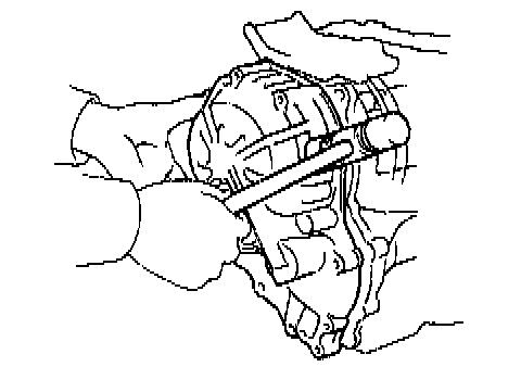
b. Tap on the circumference of the overdrive case with a plastic hammer to remove the overdrive case and gasket.

c. Remove the overdrive planetary gear from transaxle case.

d. Remove the overdrive brake drum from the transaxle case.
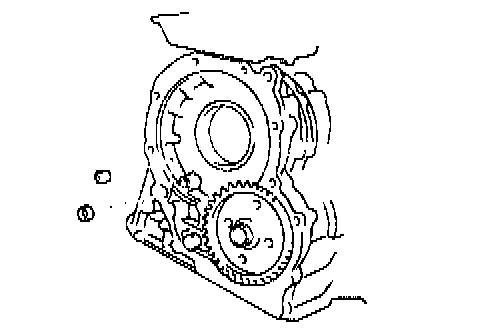
e. Remove the overdrive clutch apply gasket and overdrive brake apply gasket.
43. REMOVE FIRST AND REVERSE BRAKE PISTON
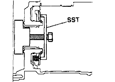
a. Remove the piston return spring. Place SST, compress the return spring evenly by tightening the bolt gradually.
SST 09350-32014 (09351-32040)

- Using snap ring Pliers, remove the snap ring.
- Remove SST.
- Remove the return spring from the case.

b. Apply compressed air into the passage of the case to remove the piston.
HINT: Hold the piston so it is not slanted and blow with the gun slightly away from the oil hole.
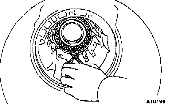
c. If the piston does not pop out with compressed air, use needle-nose pliers to remove it.

d. Remove the two O-rings from the piston.
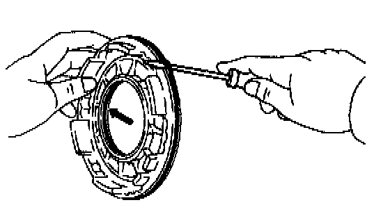
44. REMOVE SNAP RING FROM TRANSAXLE CASE
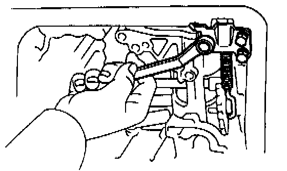
45. REMOVE PARKING LOCK PAWL BRACKET
46. REMOVE MANUAL VALVE SHAFT
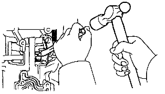
a. Using a cold chisel and hammer, cut the collar.
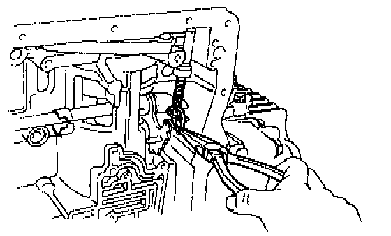
b. Remove the retaining spring.
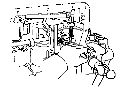
c. Using a pin punch and hammer, drive out the pin.
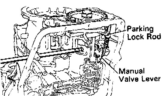
d. Slide out the shaft from the transaxle case and remove the manual valve lever and parking lock rod.

47. REMOVE MANUAL VALVE SHAFT OIL SEAL
Using a screwdriver, remove the oil seal.
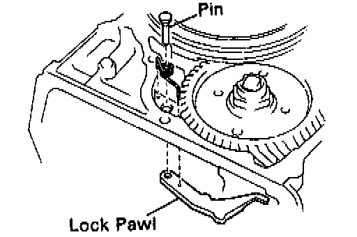
48. REMOVE PIN, SPRING AND PARKING LOCK PAWL
Differential Component Parts Removal

1. MEASURE DIFFERENTIAL TOTAL PRELOAD
Using a torque meter, measure the total preload and make a note of it.
2. REMOVE LH BEARING RETAINER
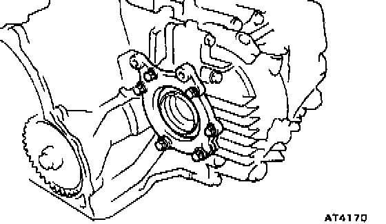
a. Remove the six bolts.

b. Using a large screwdriver, remove the LH bearing retainer.
NOTICE: Wrap the screwdriver in a rag, etc. to avoid damage t the case and retainer.
3. REMOVE RH RETAINER
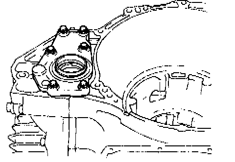
a. Remove the six bolts.
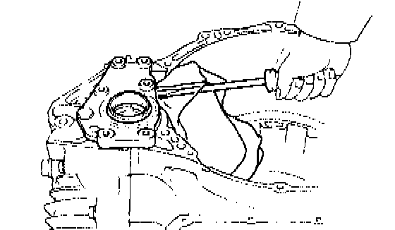
b. Using a large screwdriver, remove the RH retainer.
NOTICE: Wrap the screwdriver in a rag, etc. to avoid damage to case and retainer.
4. REMOVE CARRIER COVER
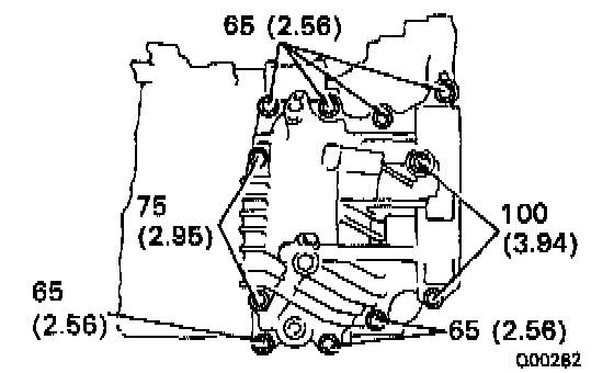
a. Remove the eleven bolts.

b. Tap the carrier cover with a plastic hammer to remove it.
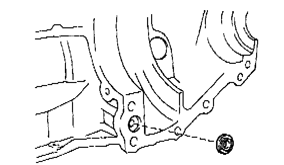
c. Remove the apply gasket.

5. REMOVE DIFFERENTIAL CASE
Remove the differential case, outer case and shim from the transaxle case.
6. REMOVE DRIVE PINION CAP
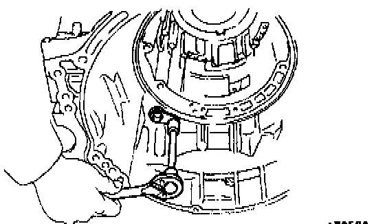
a. Remove the bolt.
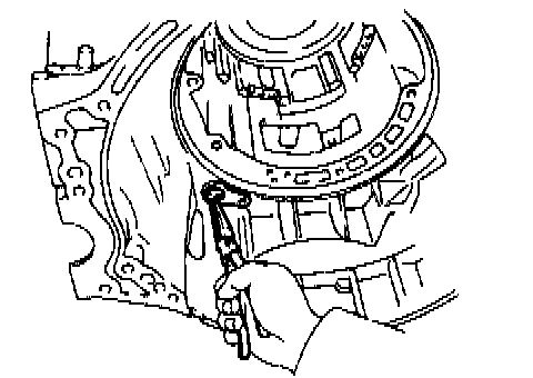
b. Using pliers, pull out the drive pinion cap.
c. Remove the O-rings from the cap.
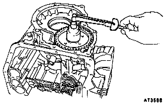
7. MEASURE DRIVE PINION PRELOAD
Using a torque meter, measure the drive pinion preload.
Preload (at starting):
Roused bearing 0.5 - 0.8 Nm (5 - 8 kgf-cm, 4.3 - 6.9 inch lbs.)
The total preload measured in step 1 minus the drive pinion preload equals 0.1 - 0.2 Nm (1.3 - 2.0 kgf-cm, 1.1 - 1.7 inch lbs.). If the result is not within this specification, the side bearing preload is bad.
8. REMOVE COUNTER DRIVEN GEAR

a. Using a chisel, loosen the staked part of the nut.
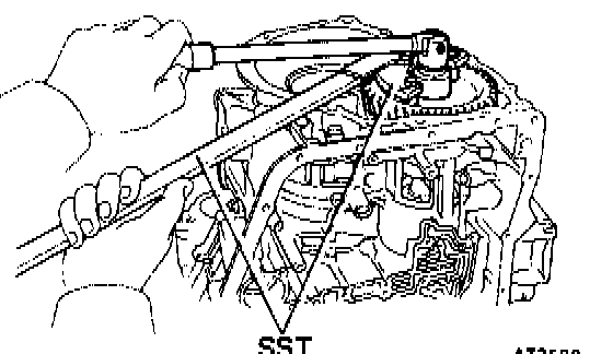
b. Using Special Service Tool (SST) to hold the gear, remove the nut.
SST 09330-00021, 09350-32014 (09351-32032)
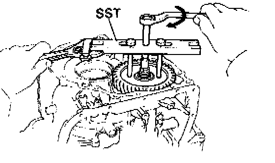
c. Using SST, remove the gear and bearing.
SST 09350-32014 (09351-32061)
9. REMOVE OUTER RACE, SPACER AND OIL SLINGER
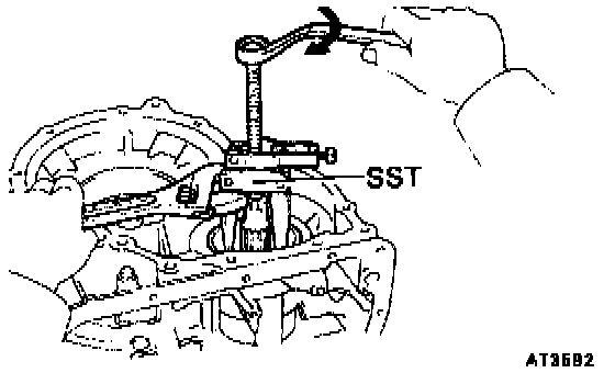
a. Using SST, remove the outer race.
SST 09350-32014 (09308-10010)
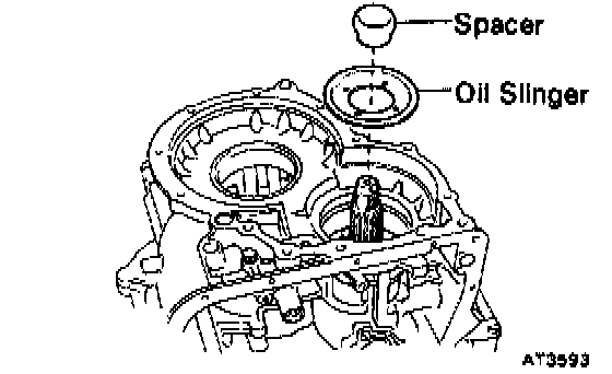
b. Remove the spacer and oil slinger.
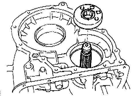
10. REMOVE SENSOR ROTOR
11. REMOVE DRIVE PINION
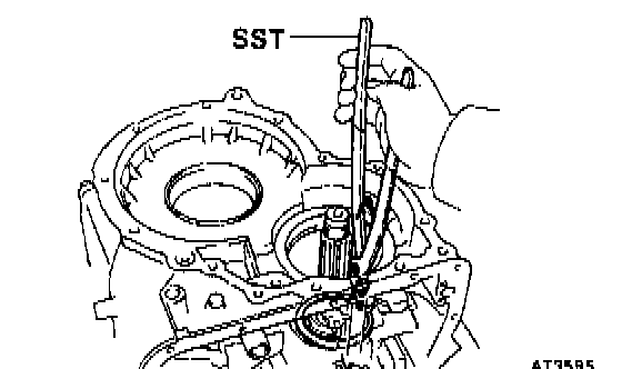
a. Using SST, remove the snap ring.
SST 09350-32014 (09351-32050)
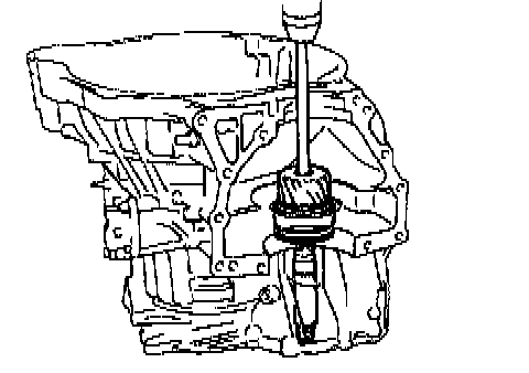
b. Install the bar into the case hole to drive out the drive pinion.
c. Using a press, drive out the drive pinion from transaxle case.
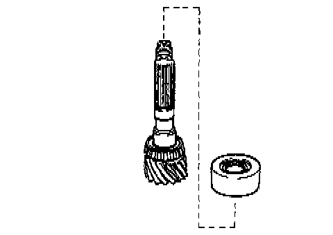
d. Remove the bearing cage from drive pinion.
42. REMOVE OVERDRIVE UNIT
a. Remove the thirteen bolts.
b. Tap on the circumference of the overdrive case with a plastic hammer to remove the overdrive case and gasket.
c. Remove the overdrive planetary gear from transaxle case.
d. Remove the overdrive brake drum from the transaxle case.
e. Remove the overdrive clutch apply gasket and overdrive brake apply gasket.
43. REMOVE FIRST AND REVERSE BRAKE PISTON
a. Remove the piston return spring. Place SST, compress the return spring evenly by tightening the bolt gradually.
SST 09350-32014 (09351-32040)
- Using snap ring Pliers, remove the snap ring.
- Remove SST.
- Remove the return spring from the case.
b. Apply compressed air into the passage of the case to remove the piston.
HINT: Hold the piston so it is not slanted and blow with the gun slightly away from the oil hole.
c. If the piston does not pop out with compressed air, use needle-nose pliers to remove it.
d. Remove the two O-rings from the piston.
44. REMOVE SNAP RING FROM TRANSAXLE CASE
45. REMOVE PARKING LOCK PAWL BRACKET
46. REMOVE MANUAL VALVE SHAFT
a. Using a cold chisel and hammer, cut the collar.
b. Remove the retaining spring.
c. Using a pin punch and hammer, drive out the pin.
d. Slide out the shaft from the transaxle case and remove the manual valve lever and parking lock rod.
47. REMOVE MANUAL VALVE SHAFT OIL SEAL
Using a screwdriver, remove the oil seal.
48. REMOVE PIN, SPRING AND PARKING LOCK PAWL
Differential Component Parts Removal
1. MEASURE DIFFERENTIAL TOTAL PRELOAD
Using a torque meter, measure the total preload and make a note of it.
2. REMOVE LH BEARING RETAINER
a. Remove the six bolts.
b. Using a large screwdriver, remove the LH bearing retainer.
NOTICE: Wrap the screwdriver in a rag, etc. to avoid damage t the case and retainer.
3. REMOVE RH RETAINER
a. Remove the six bolts.
b. Using a large screwdriver, remove the RH retainer.
NOTICE: Wrap the screwdriver in a rag, etc. to avoid damage to case and retainer.
4. REMOVE CARRIER COVER
a. Remove the eleven bolts.
b. Tap the carrier cover with a plastic hammer to remove it.
c. Remove the apply gasket.
5. REMOVE DIFFERENTIAL CASE
Remove the differential case, outer case and shim from the transaxle case.
6. REMOVE DRIVE PINION CAP
a. Remove the bolt.
b. Using pliers, pull out the drive pinion cap.
c. Remove the O-rings from the cap.
7. MEASURE DRIVE PINION PRELOAD
Using a torque meter, measure the drive pinion preload.
Preload (at starting):
Roused bearing 0.5 - 0.8 Nm (5 - 8 kgf-cm, 4.3 - 6.9 inch lbs.)
The total preload measured in step 1 minus the drive pinion preload equals 0.1 - 0.2 Nm (1.3 - 2.0 kgf-cm, 1.1 - 1.7 inch lbs.). If the result is not within this specification, the side bearing preload is bad.
8. REMOVE COUNTER DRIVEN GEAR
a. Using a chisel, loosen the staked part of the nut.
b. Using Special Service Tool (SST) to hold the gear, remove the nut.
SST 09330-00021, 09350-32014 (09351-32032)
c. Using SST, remove the gear and bearing.
SST 09350-32014 (09351-32061)
9. REMOVE OUTER RACE, SPACER AND OIL SLINGER
a. Using SST, remove the outer race.
SST 09350-32014 (09308-10010)
b. Remove the spacer and oil slinger.
10. REMOVE SENSOR ROTOR
11. REMOVE DRIVE PINION
a. Using SST, remove the snap ring.
SST 09350-32014 (09351-32050)
b. Install the bar into the case hole to drive out the drive pinion.
c. Using a press, drive out the drive pinion from transaxle case.
d. Remove the bearing cage from drive pinion.
Factory Service Tools
Use the Manual With the Right Hardware
Pair factory procedures with proven DIY tools so the instructions are easier to execute.
Disclosure: Verified tool recommendations may earn an affiliate commission at no cost to you.
When to See a Mechanic
Stop DIY work and contact a certified mechanic immediately if any of the following apply:
- • You smell fuel, burning insulation, or see smoke.
- • Brakes feel soft, pull hard to one side, or make grinding noises.
- • The engine overheats, stalls repeatedly, or misfires under load.
- • You are missing required tools, torque specs, or safe lifting equipment.
- • You are not confident in the next step or safety outcome.
Rather have a pro handle this?
A certified mobile mechanic comes to your home or office. They bring the tools, you stay comfortable. No tow truck, no waiting room, no surprises.
Comes to youSame-day available12-month warranty
Get a Free QuoteNo obligation. See pricing before you book.