
Safety Warning
DIY auto repair can cause serious injury, fire, or vehicle damage. These guides are for informational purposes only. Always follow OEM torque specs, wear PPE, and consult a certified mechanic if you are unsure. You are solely responsible for your safety.
2000 Toyota Sienna LE V6-3.0L (1MZ-FE)FACTORY OEM SERVICE PROCEDURE
Part 1
COMPONENT PARTS REMOVAL
Components
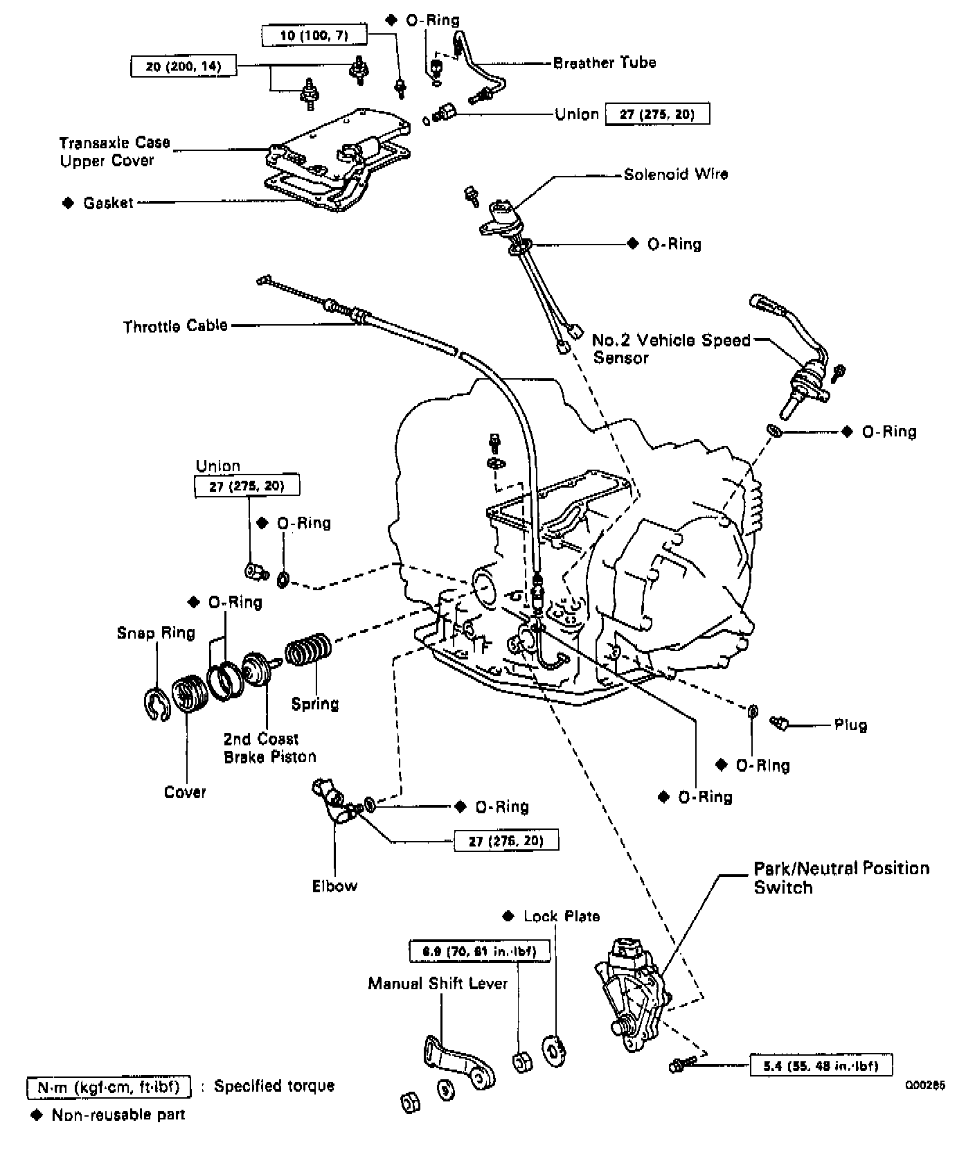


Separate Basic Subassembly
1. REMOVE UNION AND ELBOW

a. Remove the manual shift lever.

b. Using the open and wrench, remove the union and elbow.
c. Remove the O-rings from the union and elbow.
2. REMOVE PARK/NEUTRAL POSITION SWITCH
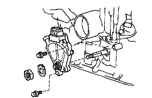
a. Pry off the lock washer and remove the manual valve shaft nut.
b. Remove the two bolts and pull out the park/neutral position switch.

3. REMOVE THROTTLE CABLE RETAINING BOLT AND PLATE

4. REMOVE NO.2 VEHICLE SPEED SENSOR
a. Remove the bolt and pull out the vehicle speed sensor.
b. Remove the O-ring from the vehicle speed sensor.
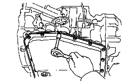
5. REMOVE OIL PAN AND GASKET
a. Remove the seventeen bolts.
b. Remove the oil pan by lifting transaxle case.
NOTICE: Do not turn the transaxle over as this will contaminate the valve body with the foreign materials in the bottom of the oil pan.
c. Place the transaxle on wooden blocks to prevent damage to the oil tube bracket.

6. EXHAUST PARTICLES IN PAN
Remove the magnet and use it to collect any steel chips.
Lock carefully at the chips and particles in the oil pan and on magnet to anticipate what type of wear you will find in the transaxle.
- Steel (magnetic): bearing, gear and plate wear
- Brass (non-magnetic): bushing wear
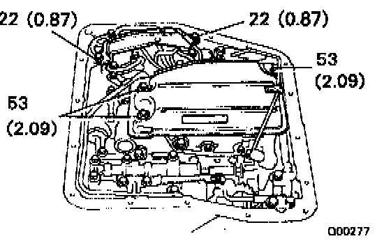
7. REMOVE OIL TUBE BRACKET AND STRAINER
8. REMOVE MANUAL VALVE BODY
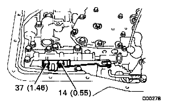
a. Remove the two bolts and detent spring.

b. Remove the five bolts and manual valve body with the manual valve.
c. Remove the manual valve from the manual valve body.
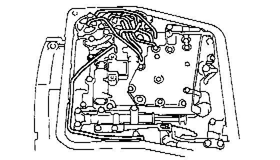
9. REMOVE OIL TUBES
a. Remove the bolt.
b. Pry up both tube ends with a large screwdriver and remove the seven tubes.

10. DISCONNECT SOLENOID CONNECTORS

11. REMOVE CONNECTOR CLAMP AND TUBE RETAINER

12. REMOVE B3 APPLY TUBE
Pry up the tube with a screwdriver and remove the tube.
13. REMOVE VALVE BODY

a. Remove the ten bolts.

b. Disconnect the throttle cable from the cam and remove the valve body.

14. REMOVE THROTTLE CABLE

15. REMOVE SOLENOID WIRING
Remove the bolt and the solenoid wiring.

16. REMOVE SECOND BRAKE APPLY GASKET
17. REMOVE ACCUMULATOR PISTONS AND SPRINGS

a. Loosen the five bolts one turn at a time until the spring tension is released.
b. Remove the cover and gasket.
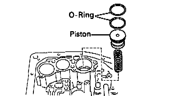
c. Remove the C1 accumulator piston and spring.
d. Remove the two O-rings from the piston.
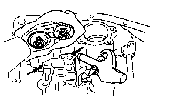
e. Pop out pistons for C and B2 into a rag, using low pressure compressed air (98 kPa, 1kgf/cm2, 14 psi). Force air into the holes shown and remove the pistons and springs.
f. Remove the O-rings from the pistons.
18. MEASURE PISTON STROKE SECOND COAST BRAKE
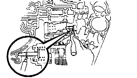
a. Apply a small amount of paint to the piston rod at the point it meets the case, as shown.
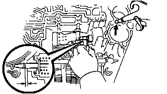
b. Using Special Service Tool (SST), measure the piston stroke applying and releasing the compressed air (392-785 kPa, 4-8 kgf/cm2, 57-114 psi), as shown.
SST 09240-00020
Maximum thrust clearance: 2.0 - 3.5 mm (0.079 - 0.138 inch)
If the piston stroke exceeds the limit, inspect the second coast brake band.
19. REMOVE SECOND COAST BRAKE PISTON

a. Using SST, remove the snap ring.
SST 09350-32014


b. Applying compressed air to the oil hole, remove the second coast brake cover, piston assembly and spring.
c. Remove the two O-rings from the cover.
20. STAND TRANSAXLE ENGINE SIDE UPWARD
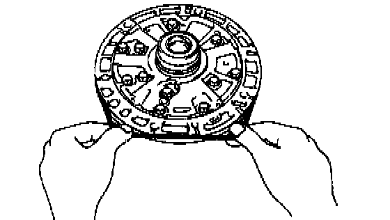
21. REMOVE OIL PUMP
NOTICE: Before removing the oil pump, remove the second coast brake piston.

a. Remove the seven bolts.

b. Using SST, pull out the oil pump from the transaxle case.
SST 09350-32014
22. REMOVE O-RING FROM OIL PUMP

23. REMOVE DIRECT CLUTCH AND FORWARD CLUTCH

24. SEPARATE DIRECT CLUTCH AND FORWARD CLUTCH
a. Separate the direct clutch and forward clutch.
b. Remove the thrust washer from direct clutch.

25. REMOVE BEARING FROM FORWARD CLUTCH

26. REMOVE SECOND COAST BRAKE BAND
a. Push the pin with a small screwdriver and remove it from the bolt hole of the oil pump mounting.
b. Remove the brake band.
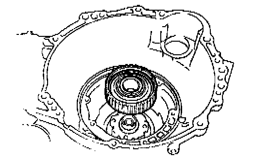
27. REMOVE FRONT PLANETARY RING GEAR
28. REMOVE FRONT PLANETARY GEAR
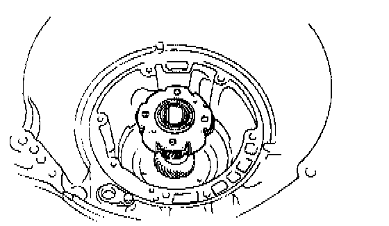
a. Remove the front planetary gear.

b. Remove the two bearings from the planetary gear.
29. REMOVE SUN GEAR AND SUN GEAR INPUT DRUM

a. Remove the sun gear and the sun gear input drum.
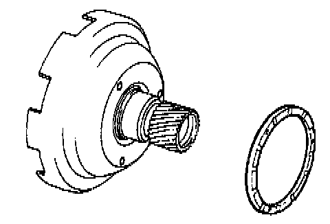
b. Remove the thrust washer from sun gear input drum.

30. CHECK OPERATION OF SECOND BRAKE PISTON
Apply compressed air into the case passage and confirm that the piston moves.
If the piston does not move, disassemble and inspect.

31. REMOVE SECOND COAST BRAKE BAND GUIDE
32. REMOVE SECOND BRAKE DRUM
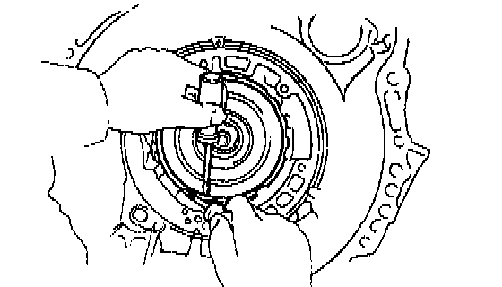
a. Remove the snap ring.
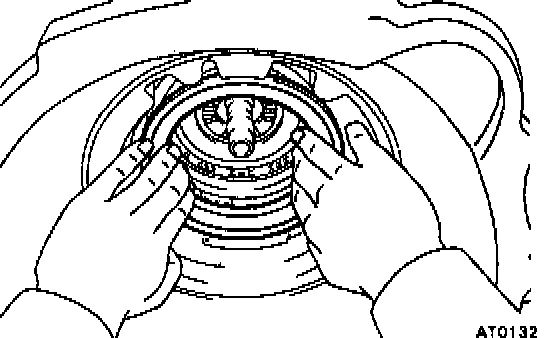
b. Remove the second brake drum.
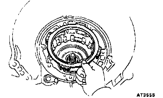
33. REMOVE SECOND BRAKE PISTON RETURN SPRING

34. REMOVE NO.1 ONE-WAY CLUTCH

35. REMOVE PLATES, DISCS AND FLANGE

36. REMOVE SECOND BRAKE DRUM GASKET
Remove the gasket.
37. REMOVE NO.2 ONE-WAY CLUTCH AND REAR PLANETARY GEAR
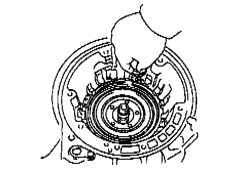
a. Remove the snap ring.
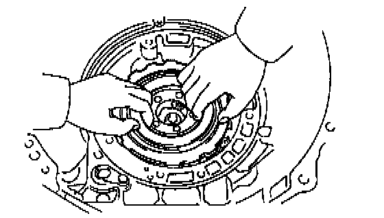
b. Remove the No.2 one-way clutch and rear planetary gear.

c. Remove two thrust washers from the rear planetary gear.
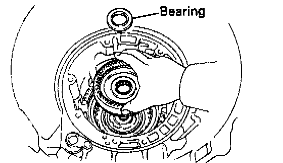
38. REMOVE REAR PLANETARY RING GEAR
a. Remove the rear planetary ring gear.
b. Remove the bearing from the ring gear.
39. CHECK FIRST AND REVERSE BRAKE

a. Check the operation of the first and reverse brake piston.
Apply compressed air into the case passage and confirm that the piston moves.
If the piston does not move, disassemble and inspect.

b. Using a feeler gauge, check the pack clearance of the first and reverse brake.
Clearance: 0.85 - 2.05 mm (0.033 - 0.081 inch)
40. REMOVE FLANGE, DISCS AND PLATES OF FIRST AND REVERSE BRAKE

a. Remove the snap ring.

b. Remove the flange, seven discs and seven plates.
Components
Separate Basic Subassembly
1. REMOVE UNION AND ELBOW
a. Remove the manual shift lever.
b. Using the open and wrench, remove the union and elbow.
c. Remove the O-rings from the union and elbow.
2. REMOVE PARK/NEUTRAL POSITION SWITCH
a. Pry off the lock washer and remove the manual valve shaft nut.
b. Remove the two bolts and pull out the park/neutral position switch.
3. REMOVE THROTTLE CABLE RETAINING BOLT AND PLATE
4. REMOVE NO.2 VEHICLE SPEED SENSOR
a. Remove the bolt and pull out the vehicle speed sensor.
b. Remove the O-ring from the vehicle speed sensor.
5. REMOVE OIL PAN AND GASKET
a. Remove the seventeen bolts.
b. Remove the oil pan by lifting transaxle case.
NOTICE: Do not turn the transaxle over as this will contaminate the valve body with the foreign materials in the bottom of the oil pan.
c. Place the transaxle on wooden blocks to prevent damage to the oil tube bracket.
6. EXHAUST PARTICLES IN PAN
Remove the magnet and use it to collect any steel chips.
Lock carefully at the chips and particles in the oil pan and on magnet to anticipate what type of wear you will find in the transaxle.
- Steel (magnetic): bearing, gear and plate wear
- Brass (non-magnetic): bushing wear
7. REMOVE OIL TUBE BRACKET AND STRAINER
8. REMOVE MANUAL VALVE BODY
a. Remove the two bolts and detent spring.
b. Remove the five bolts and manual valve body with the manual valve.
c. Remove the manual valve from the manual valve body.
9. REMOVE OIL TUBES
a. Remove the bolt.
b. Pry up both tube ends with a large screwdriver and remove the seven tubes.
10. DISCONNECT SOLENOID CONNECTORS
11. REMOVE CONNECTOR CLAMP AND TUBE RETAINER
12. REMOVE B3 APPLY TUBE
Pry up the tube with a screwdriver and remove the tube.
13. REMOVE VALVE BODY
a. Remove the ten bolts.
b. Disconnect the throttle cable from the cam and remove the valve body.
14. REMOVE THROTTLE CABLE
15. REMOVE SOLENOID WIRING
Remove the bolt and the solenoid wiring.
16. REMOVE SECOND BRAKE APPLY GASKET
17. REMOVE ACCUMULATOR PISTONS AND SPRINGS
a. Loosen the five bolts one turn at a time until the spring tension is released.
b. Remove the cover and gasket.
c. Remove the C1 accumulator piston and spring.
d. Remove the two O-rings from the piston.
e. Pop out pistons for C and B2 into a rag, using low pressure compressed air (98 kPa, 1kgf/cm2, 14 psi). Force air into the holes shown and remove the pistons and springs.
f. Remove the O-rings from the pistons.
18. MEASURE PISTON STROKE SECOND COAST BRAKE
a. Apply a small amount of paint to the piston rod at the point it meets the case, as shown.
b. Using Special Service Tool (SST), measure the piston stroke applying and releasing the compressed air (392-785 kPa, 4-8 kgf/cm2, 57-114 psi), as shown.
SST 09240-00020
Maximum thrust clearance: 2.0 - 3.5 mm (0.079 - 0.138 inch)
If the piston stroke exceeds the limit, inspect the second coast brake band.
19. REMOVE SECOND COAST BRAKE PISTON
a. Using SST, remove the snap ring.
SST 09350-32014
b. Applying compressed air to the oil hole, remove the second coast brake cover, piston assembly and spring.
c. Remove the two O-rings from the cover.
20. STAND TRANSAXLE ENGINE SIDE UPWARD
21. REMOVE OIL PUMP
NOTICE: Before removing the oil pump, remove the second coast brake piston.
a. Remove the seven bolts.
b. Using SST, pull out the oil pump from the transaxle case.
SST 09350-32014
22. REMOVE O-RING FROM OIL PUMP
23. REMOVE DIRECT CLUTCH AND FORWARD CLUTCH
24. SEPARATE DIRECT CLUTCH AND FORWARD CLUTCH
a. Separate the direct clutch and forward clutch.
b. Remove the thrust washer from direct clutch.
25. REMOVE BEARING FROM FORWARD CLUTCH
26. REMOVE SECOND COAST BRAKE BAND
a. Push the pin with a small screwdriver and remove it from the bolt hole of the oil pump mounting.
b. Remove the brake band.
27. REMOVE FRONT PLANETARY RING GEAR
28. REMOVE FRONT PLANETARY GEAR
a. Remove the front planetary gear.
b. Remove the two bearings from the planetary gear.
29. REMOVE SUN GEAR AND SUN GEAR INPUT DRUM
a. Remove the sun gear and the sun gear input drum.
b. Remove the thrust washer from sun gear input drum.
30. CHECK OPERATION OF SECOND BRAKE PISTON
Apply compressed air into the case passage and confirm that the piston moves.
If the piston does not move, disassemble and inspect.
31. REMOVE SECOND COAST BRAKE BAND GUIDE
32. REMOVE SECOND BRAKE DRUM
a. Remove the snap ring.
b. Remove the second brake drum.
33. REMOVE SECOND BRAKE PISTON RETURN SPRING
34. REMOVE NO.1 ONE-WAY CLUTCH
35. REMOVE PLATES, DISCS AND FLANGE
36. REMOVE SECOND BRAKE DRUM GASKET
Remove the gasket.
37. REMOVE NO.2 ONE-WAY CLUTCH AND REAR PLANETARY GEAR
a. Remove the snap ring.
b. Remove the No.2 one-way clutch and rear planetary gear.
c. Remove two thrust washers from the rear planetary gear.
38. REMOVE REAR PLANETARY RING GEAR
a. Remove the rear planetary ring gear.
b. Remove the bearing from the ring gear.
39. CHECK FIRST AND REVERSE BRAKE
a. Check the operation of the first and reverse brake piston.
Apply compressed air into the case passage and confirm that the piston moves.
If the piston does not move, disassemble and inspect.
b. Using a feeler gauge, check the pack clearance of the first and reverse brake.
Clearance: 0.85 - 2.05 mm (0.033 - 0.081 inch)
40. REMOVE FLANGE, DISCS AND PLATES OF FIRST AND REVERSE BRAKE
a. Remove the snap ring.
b. Remove the flange, seven discs and seven plates.
Factory Service Tools
Use the Manual With the Right Hardware
Pair factory procedures with proven DIY tools so the instructions are easier to execute.
Disclosure: Verified tool recommendations may earn an affiliate commission at no cost to you.
When to See a Mechanic
Stop DIY work and contact a certified mechanic immediately if any of the following apply:
- • You smell fuel, burning insulation, or see smoke.
- • Brakes feel soft, pull hard to one side, or make grinding noises.
- • The engine overheats, stalls repeatedly, or misfires under load.
- • You are missing required tools, torque specs, or safe lifting equipment.
- • You are not confident in the next step or safety outcome.
Rather have a pro handle this?
A certified mobile mechanic comes to your home or office. They bring the tools, you stay comfortable. No tow truck, no waiting room, no surprises.
Comes to youSame-day available12-month warranty
Get a Free QuoteNo obligation. See pricing before you book.