
Safety Warning
DIY auto repair can cause serious injury, fire, or vehicle damage. These guides are for informational purposes only. Always follow OEM torque specs, wear PPE, and consult a certified mechanic if you are unsure. You are solely responsible for your safety.
2000 Toyota Sienna LE V6-3.0L (1MZ-FE)FACTORY OEM SERVICE PROCEDURE
Disassembly
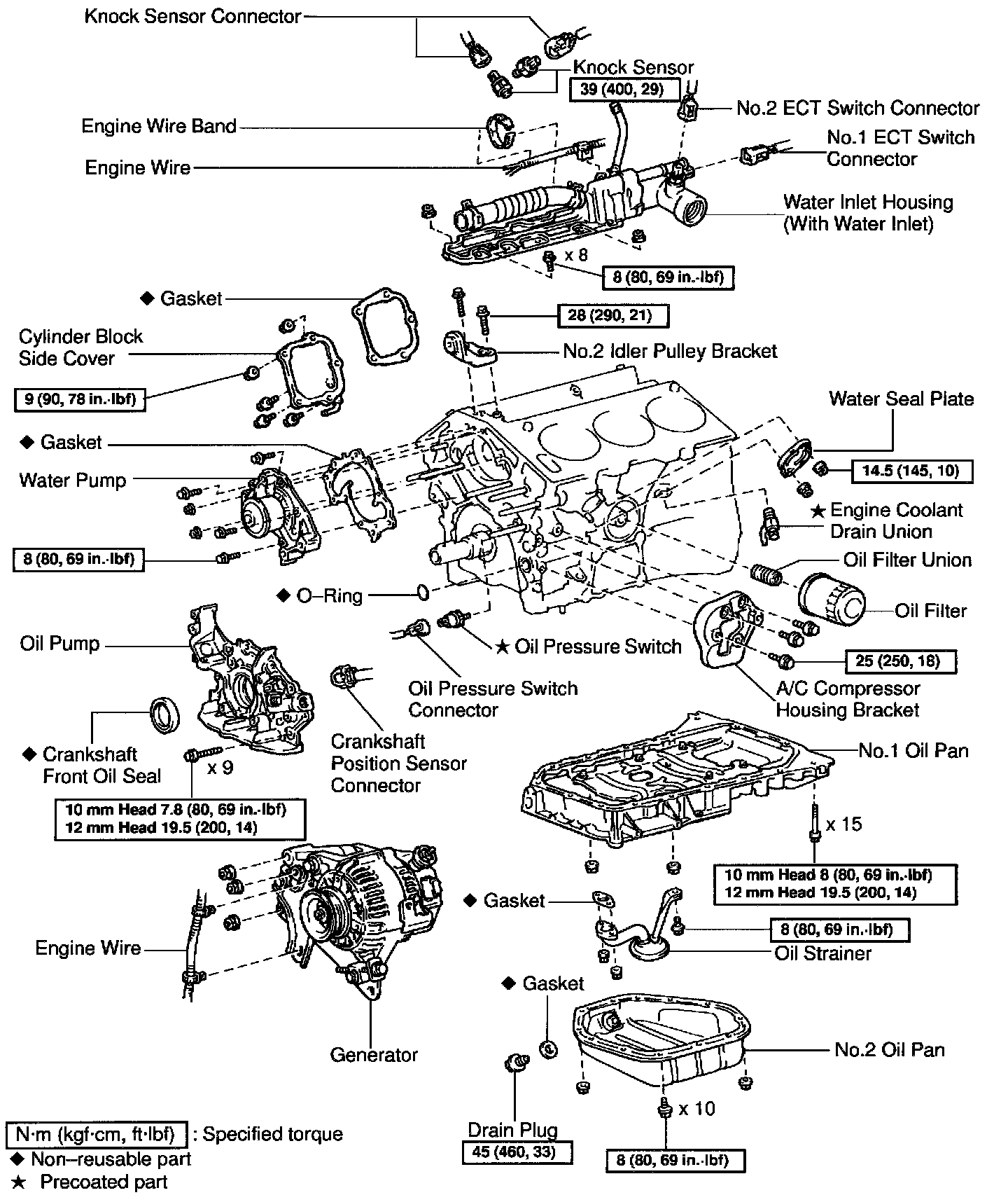
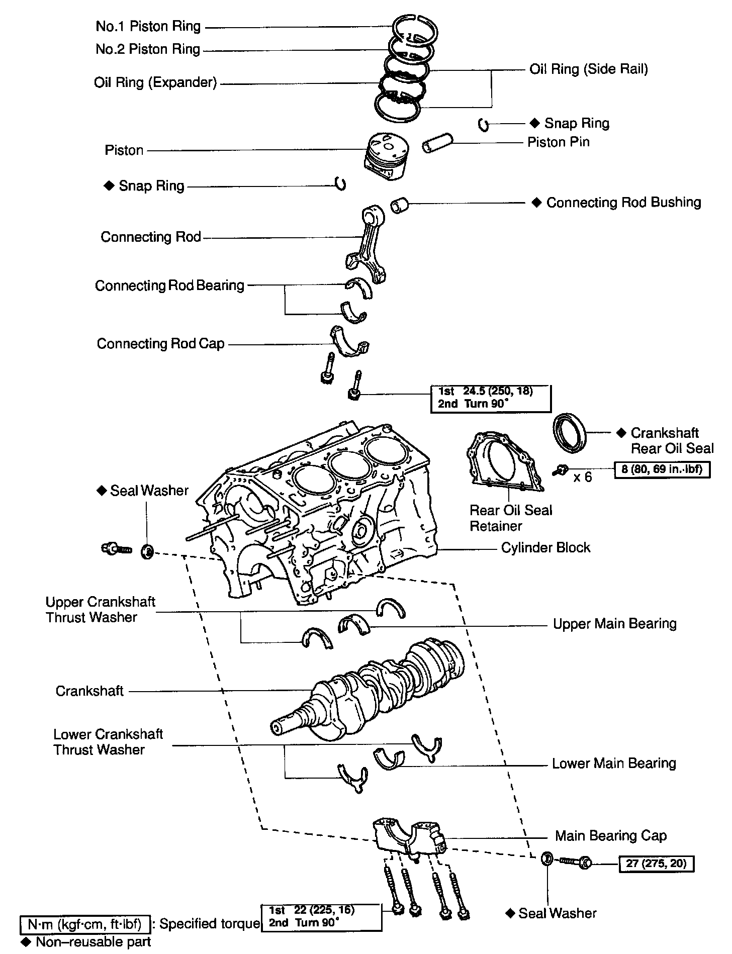
DISASSEMBLY
1. INSTALL ENGINE TO ENGINE STAND FOR DISASSEMBLY
2. REMOVE TIMING BELT AND PULLEYS
3. REMOVE CYLINDER HEAD
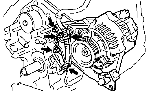
4. REMOVE GENERATOR, ADJUSTING BAR AND BRACKET ASSEMBLY
a. Disconnect the 2 wire clamps from the wire brackets.
b. Remove the 3 nuts, the generator, adjusting bar and bracket assembly.
5. REMOVE OIL PRESSURE SWITCH
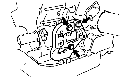
6. REMOVE A/C COMPRESSOR HOUSING BRACKET
Remove the 3 bolts and compressor housing bracket.
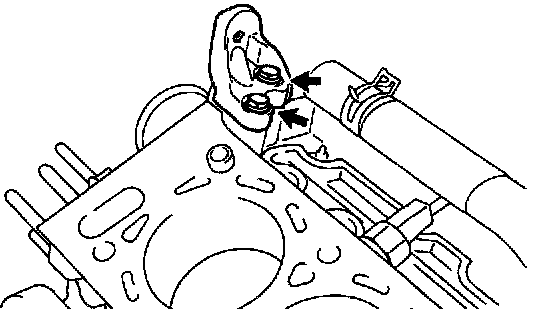
7. REMOVE NO.2 IDLER PULLEY BRACKET
Remove the 2 bolts and idler pulley bracket.
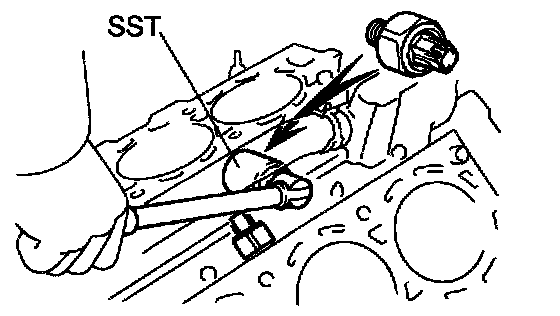
8. REMOVE KNOCK SENSORS
a. Disconnect the 2 knock sensor connectors.
b. Using SST, remove the 2 knock sensors.
SST 09816-30010
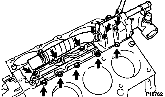
9. REMOVE WATER INLET HOUSING
a. Remove the engine wire band.
b. Disconnect the engine wire clamp from the bracket.
c. Remove the 8 bolts, 2 nuts and water inlet housing.
10. REMOVE WATER PUMP
11. REMOVE NO.2 OIL PAN
12. REMOVE OIL STRAINER
13. REMOVE NO.1 OIL PAN
14. REMOVE OIL PUMP
15. REMOVE OIL FILTER
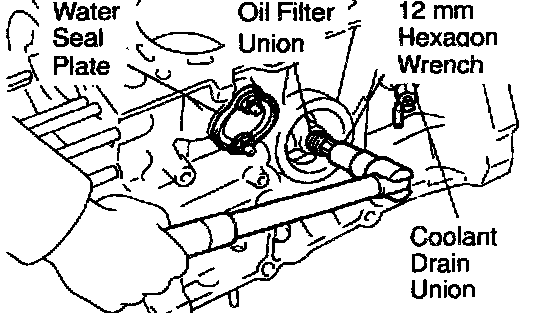
16. REMOVE OIL FILTER UNION
Using a 12 mm hexagon wrench, remove the oil filter union.
17. REMOVE WATER SEAL PLATE
Remove the 2 nuts and seal plate.
18. REMOVE ENGINE COOLANT DRAIN UNION
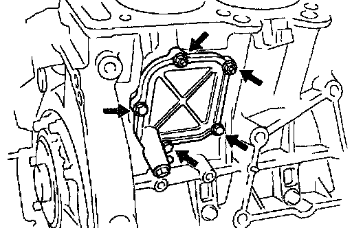
19. REMOVE CYLINDER BLOCK SIDE COVER
Remove the 3 bolts, 2 nuts, cylinder block side cover and gasket.
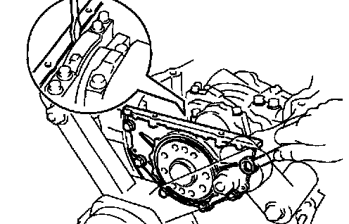
20. REMOVE REAR OIL SEAL RETAINER
a. Remove the 6 bolts.
b. Using a screwdriver, remove the oil seal retainer by prying the portions between the oil seal retainer and main bearing cap.

21. CHECK CONNECTING ROD THRUST CLEARANCE
Using a dial indicator, measure the thrust clearance while moving the connecting rod back and forth.
Standard thrust clearance: 0.15 - 0.30 mm (0.0059 - 0.0118 inch)
Maximum thrust clearance: 0.35 mm (0.0138 inch)
If the thrust clearance is greater than maximum, replace the connecting rod assembly(s). If necessary, replace the crankshaft.
Connecting rod thickness: 20.80 - 20.85 mm (0.8189 - 0.8209 inch)
22. REMOVE CONNECTING ROD CAPS AND CHECK OIL CLEARANCE

a. Check the matchmarks on the connecting rod and cap are aligned to ensure correct reassembly.
b. Remove the 2 connecting rod cap bolts.
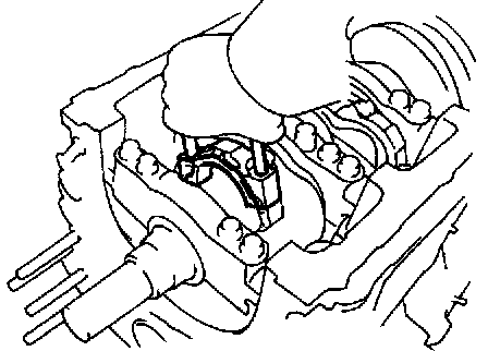
c. Using the 2 removed connecting rod cap bolts, remove the connecting rod cap and lower bearing by wiggling the connecting rod cap right and left.
HINT: Keep the lower bearing inserted with the connecting rod cap.
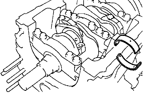
d. Clean the crank pin and bearing.
e. Check the crank pin and bearing for pitting and scratches.
If the crank pin or bearing is damaged, replace the bearings. If necessary, replace the crankshaft.

f. Lay a strip of Plastigage across the crank pin.
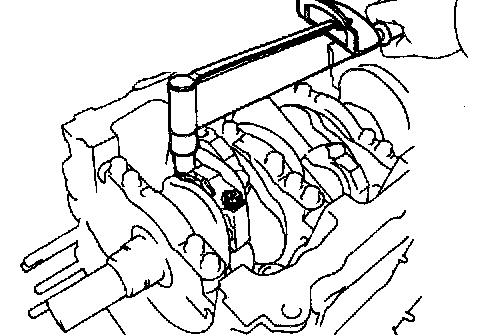
g. Install the connecting rod cap with the 2 bolts.
Torque:
1st: 24.5 Nm (250 kgf-cm, 18 ft. lbs.)
2nd: Turn extra 90°
NOTICE: Do not turn the crankshaft.
h. Remove the 2 bolts, connecting rod cap and lower bearing. (See procedure b. and c. above)
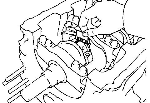
i. Measure the Plastigage at its widest point.
Standard oil clearance: 0.038 - 0.064 mm (0.0015 - 0.0025 inch)
Maximum oil clearance: 0.08 mm (0.0031 inch)
If the oil clearance is greater than maximum, replace the bearings. If necessary, grind or replace the crankshaft.

HINT: If replacing a bearing, replace it with one having the same number as marked on the connecting rod. There are 4 sizes of standard bearings, marked "1", "2", "3" and "4" accordingly.
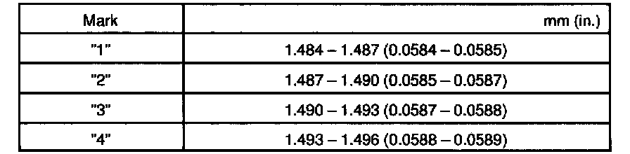
Reference:
Standard bearing center wall thickness:
j. Completely remove the Plastigage.

23. REMOVE PISTON AND CONNECTING ROD ASSEMBLIES
a. Using a ridge reamer, remove all the carbon from the top of the cylinder.
b. Push the piston, connecting rod assembly and upper bearing through the top of the cylinder block.
HINT: Keep the bearings, connecting rod and cap together.
Arrange the piston and connecting rod assemblies in the correct order.
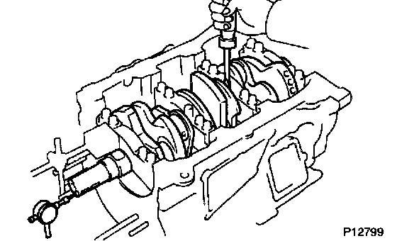
24. CHECK CRANKSHAFT THRUST CLEARANCE
Using a dial indicator, measure the thrust clearance while prying the crankshaft back and forth with a screwdriver.
Standard thrust clearance: 0.04 - 0.24 mm (0.0016 - 0.0095 inch)
Maximum thrust clearance: 0.30 mm (0.0118 inch)
If the thrust clearance is greater than maximum replace the thrust washers as a set.
Thrust washer thickness: 1.930 - 1.980 mm (0.0760 - 0.0780 inch)
25. REMOVE MAIN BEARING CAPS AND CHECK OIL CLEARANCE
Removal Sequence:

a. Uniformly loosen and remove the 8 main bearing cap bolts and seal washers in the several passes, in the sequence shown.
Removal Sequence:

b. Uniformly loosen and remove the 16 main bearing cap bolts in several passes, in the sequence shown.
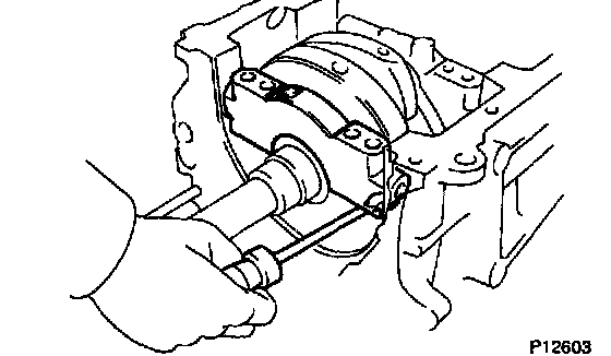
c. Using a screwdriver, pry out main bearing caps. Remove the 4 main bearing caps, lower bearings and (No. 2 main bearing cap only) 2 lower thrust washers.

NOTICE: Pull up the main bearing cap little by little to the right and the left by turns and pay attention not to damage the joint surface of the cylinder block and the main bearing cap.
HINT:
- Keep the lower bearing and main bearing cap together.
- Arrange the main bearing caps and lower thrust washers in correct order.
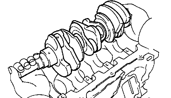
d. Lift out the crankshaft.
HINT: Keep the upper bearings together with the cylinder block.
e. Clean each main journal and bearing.
f. Check each main journal and bearing for pitting and scratches.
If the journal or bearing is damaged, replace the bearings. If necessary, replace the crankshaft.
g. Place the crankshaft on the cylinder block.
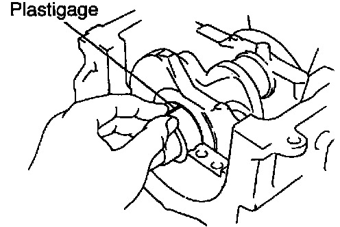
h. Lay a strip of Plastigage across each journal.

i. Install the 4 main bearing caps.
Torque:
12 pointed head bolts: 1st: 22 Nm (225 kgf-cm, 16 ft. lbs.)
2nd: Turn extra 90°
Hexagon head bolts: 27 Nm (275 kgf-cm, 20 ft. lbs.)
NOTICE: Do not turn the crankshaft.
j. Remove the main bearing caps. (See procedures a. to c. above)

k. Measure the Plastigage at its widest point.
Standard oil clearance:
No. 1 and No. 4 journals: 0.014 - 0.036 mm (0.0006 - 0.0014 inch)
No. 2 and No. 3 journals: 0.026 - 0.048 mm (0.0010 - 0.0019 inch)
Maximum clearance:
No. 1 and No. 4 journals: 0.05 mm (0.0020 inch)
No. 2 and No. 3 journals: 0.06 mm (0.0024 inch)
If the oil clearance is greater than maximum, replace the bearings. If necessary, replace the crankshaft.
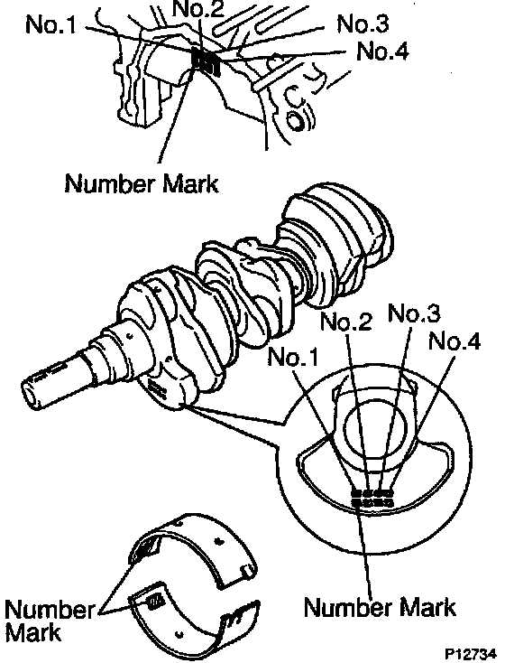
HINT: If using a bearing, replace it with one having the same number. If the number of the bearing cannot be determined, select the correct bearing by adding together the numbers imprinted on the cylinder block and crankshaft, then refer to the table for the appropriate bearing number. The No. 1 and No. 4 journal bearings have 5 standard bearing sizes, marked "3", "4", "5", "6" and "7" accordingly. The No. 2 and No. 3 journal bearings have 5 standard bearing sizes, marked "1", "2", "3", "4" and "5" accordingly.
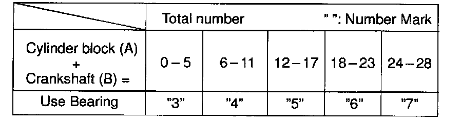
No. 1 and No. 4 journal bearings
EXAMPLE: Cylinder block "06" (A)
+ Crankshaft "08" (B)
= Total number 14 (Use bearing "5")

No. 1 and No. 4 journal standard bearings selection chart
EXAMPLE: Cylinder block "06", Crankshaft "08"
= Use bearing "5"
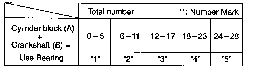
No. 2 and No. 3 journal bearings
EXAMPLE: Cylinder block "06" (A)
+ Crankshaft "08" (B)
= Total number 14 (Use bearing "3")

No. 2 and No. 3 journal standard bearings selection chart
EXAMPLE: Cylinder block "06", Crankshaft "08"
= Use bearing "3"

Reference:
1) Completely remove the Plastigage.
26. REMOVE CRANKSHAFT
a. Lift out the crankshaft.
b. Remove the 4 upper main bearings and 2 upper thrust washers from the cylinder block.
HINT: Arrange the main bearing caps, bearings and thrust washers in the correct order.
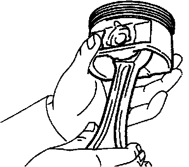
27. CHECK FIT BETWEEN PISTON AND PISTON PIN
Try to move the piston back and forth on the piston pin. If any movement is felt, replace the piston and pin as a set.
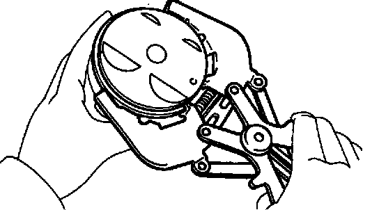
28. REMOVE PISTON RINGS
a. Using a piston ring expander, remove the 2 compression rings.
b. Remove the 2 side rails and oil ring by hand.
HINT: Arrange the piston rings in the correct order only.
29. DISCONNECT CONNECTING ROD FROM PISTON
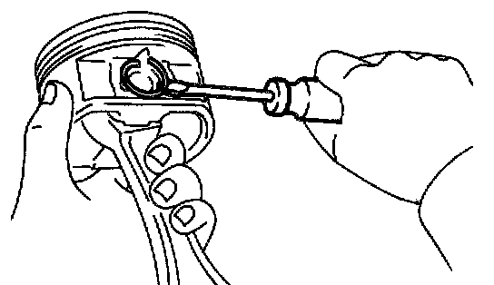
a. Using a small screwdriver, pry out the 2 snap rings.
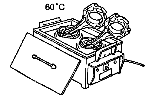
b. Gradually heat the piston to approx. 60°C (140°F).
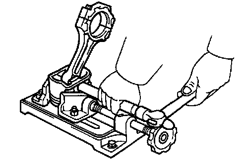
c. Using a plastic-faced hammer and brass bar, lightly tap out the piston pin and remove the connecting rod.
HINT:
- The piston and pin are a matched set.
- Arrange the pistons, pins, rings, connecting rods and bearings in the correct order.
Factory Service Tools
Use the Manual With the Right Hardware
Pair factory procedures with proven DIY tools so the instructions are easier to execute.
Disclosure: Verified tool recommendations may earn an affiliate commission at no cost to you.
When to See a Mechanic
Stop DIY work and contact a certified mechanic immediately if any of the following apply:
- • You smell fuel, burning insulation, or see smoke.
- • Brakes feel soft, pull hard to one side, or make grinding noises.
- • The engine overheats, stalls repeatedly, or misfires under load.
- • You are missing required tools, torque specs, or safe lifting equipment.
- • You are not confident in the next step or safety outcome.
Rather have a pro handle this?
A certified mobile mechanic comes to your home or office. They bring the tools, you stay comfortable. No tow truck, no waiting room, no surprises.
Comes to youSame-day available12-month warranty
Get a Free QuoteNo obligation. See pricing before you book.