
Safety Warning
DIY auto repair can cause serious injury, fire, or vehicle damage. These guides are for informational purposes only. Always follow OEM torque specs, wear PPE, and consult a certified mechanic if you are unsure. You are solely responsible for your safety.
2011 Suzuki SX4 2WD L4-2.0LFACTORY OEM SERVICE PROCEDURE
Inspection of Keyless Start Control Module and Its Circuits
Inspection of Keyless Start Control Module and Its Circuits
Keyless start control module and its circuits can be checked at keyless start control module wiring couplers by measuring voltage and resistance.
NOTE:
If you connect a voltmeter or ohmmeter directly to the keyless start control module by disconnecting the keyless start control module connector, you can damage the keyless start control module.
Never connect a voltmeter or an ohmmeter directly to any terminal on the keyless start control module by disconnecting the keyless start control module connector.
Voltage Check
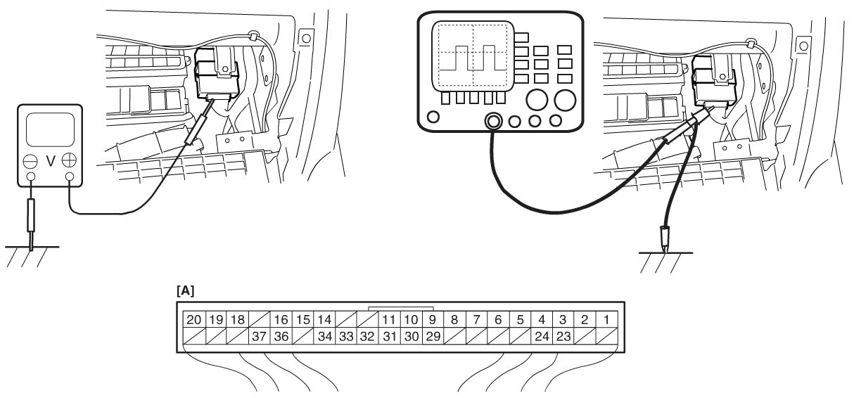
1) Disconnect negative cable (-) at battery.
2) Remove keyless start control module from vehicle body referring to Service and Repair Keyless Start Control Module Removal and Installation.
3) Connect connector to keyless start control module.
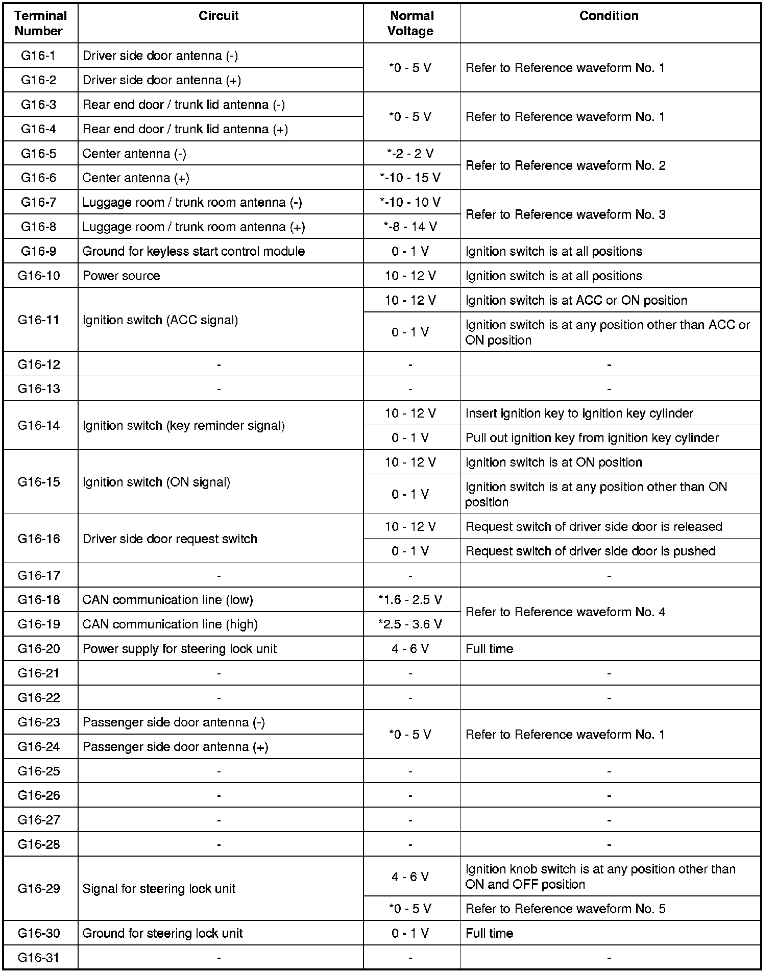
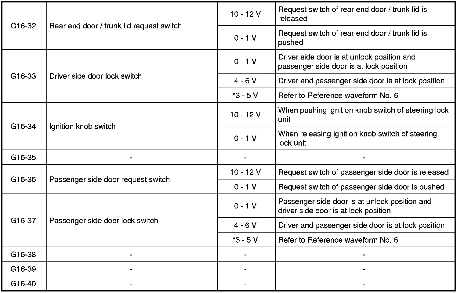
4) Check voltage at each terminal number of couplers connected.
NOTE:
- As each terminal voltage is affected by the battery voltage, confirm that it is 11 V or more when ignition switch is ON.
- Voltage with asterisk (*) cannot be measured by voltmeter because it is pulse signal.

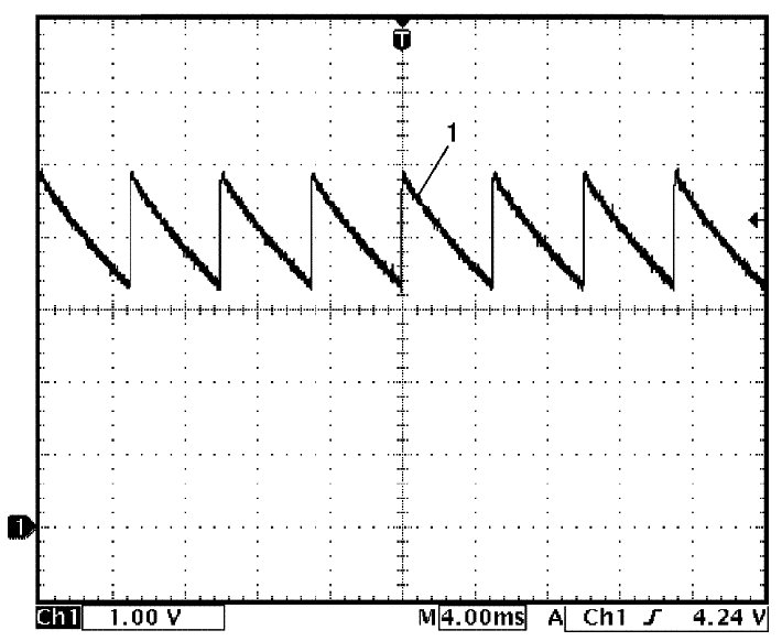
Reference Waveform
NOTE:
- Waveform analysis is as follows.
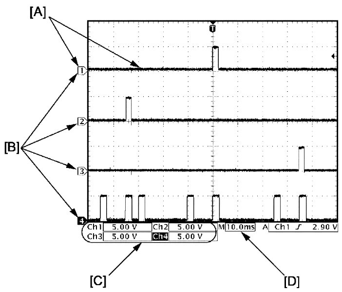

- Waveform might change for measurement condition and vehicle spec.
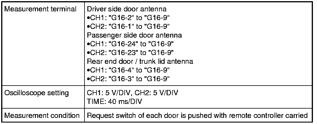
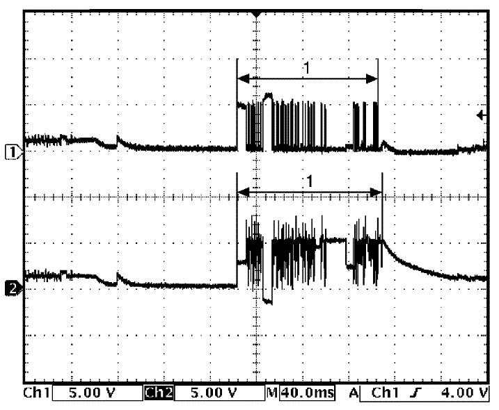
Reference waveform No. 1
Driver, passenger and rear end door / trunk lid antenna request signals (Request signal (1) transmitted by each door antenna when each door request switch is pushed)
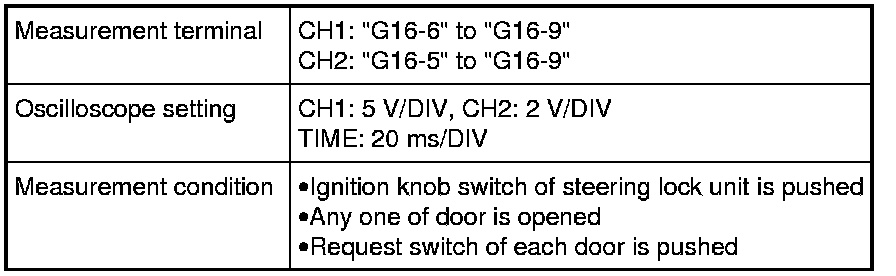
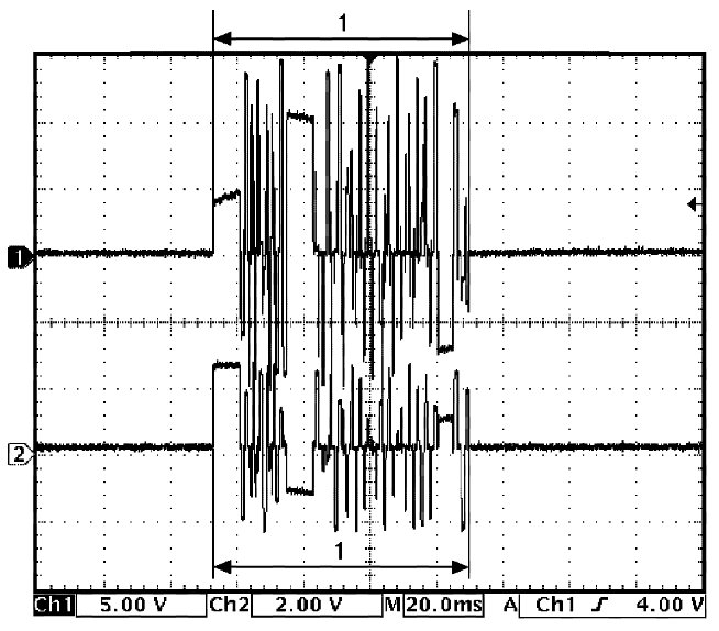
Reference waveform No. 2
Center antenna signal
(Request signal (1) transmitted by center antenna when each door request switch is pushed)
Reference waveform No. 3
Luggage room / trunk room antenna signal
(Request signal (1) transmitted by luggage room / trunk room antenna when each door request switch is pushed)
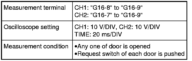
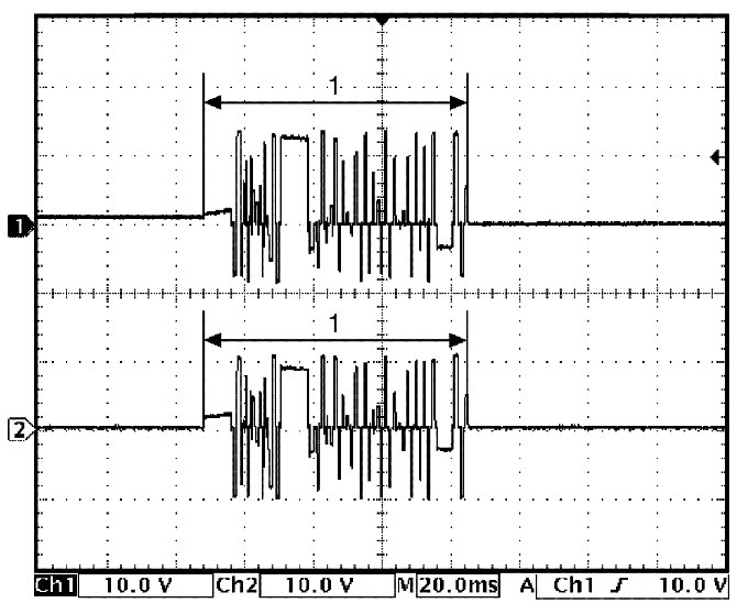
Reference waveform No. 4
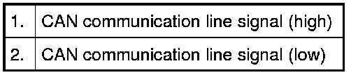
CAN communication signals
(CAN signal communicated to each control module when ignition switch is turned ON)
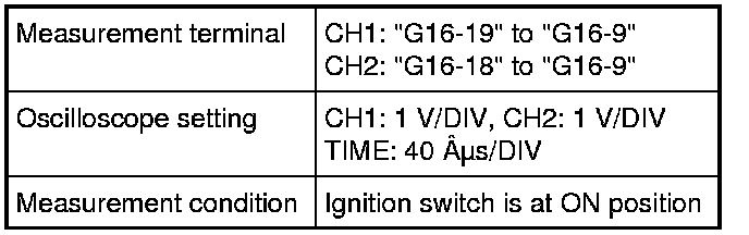
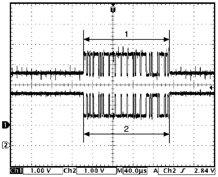
Reference waveform No. 5
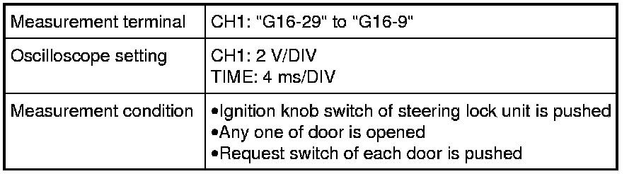
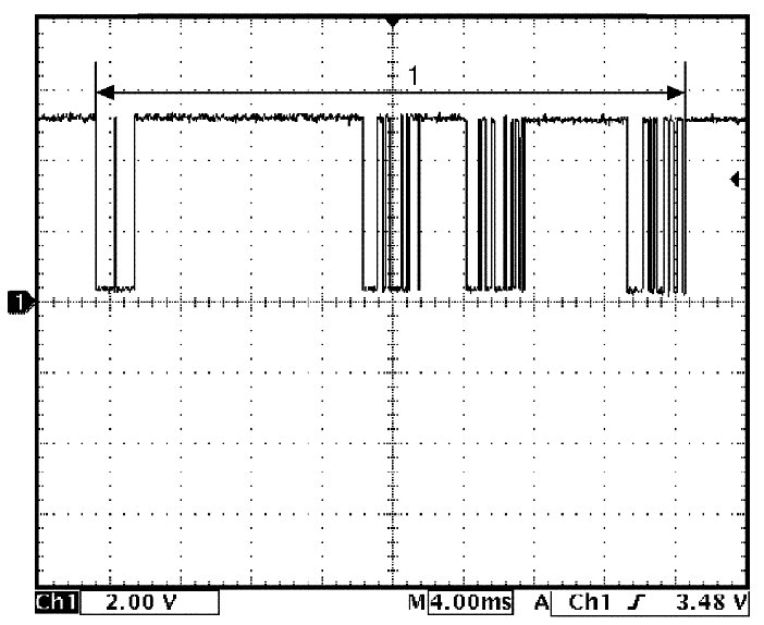
Steering lock unit signal
(Signal (1) communicated between keyless start control module and steering lock unit when measurement condition described below applies)
Reference waveform No. 6
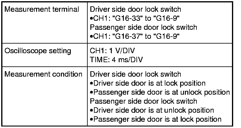
Driver side and passenger side door lock switch signals
(Signal (1) indicating door lock switch status which keyless start control module receives from BCM)
Factory Service Tools
Use the Manual With the Right Hardware
Pair factory procedures with proven DIY tools so the instructions are easier to execute.
Disclosure: Verified tool recommendations may earn an affiliate commission at no cost to you.
When to See a Mechanic
Stop DIY work and contact a certified mechanic immediately if any of the following apply:
- • You smell fuel, burning insulation, or see smoke.
- • Brakes feel soft, pull hard to one side, or make grinding noises.
- • The engine overheats, stalls repeatedly, or misfires under load.
- • You are missing required tools, torque specs, or safe lifting equipment.
- • You are not confident in the next step or safety outcome.