
Safety Warning
DIY auto repair can cause serious injury, fire, or vehicle damage. These guides are for informational purposes only. Always follow OEM torque specs, wear PPE, and consult a certified mechanic if you are unsure. You are solely responsible for your safety.
2011 Suzuki Equator 2WD L4-2.5LFACTORY OEM SERVICE PROCEDURE
System Specifications
Service Data and Specifications
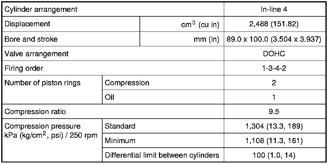
General Specifications
Drive Belt

Exhaust Manifold and Three Way Catalyst Assembly
Unit: mm (in)

Spark Plug
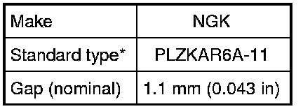
*: Always check with the Parts Department for the latest parts information
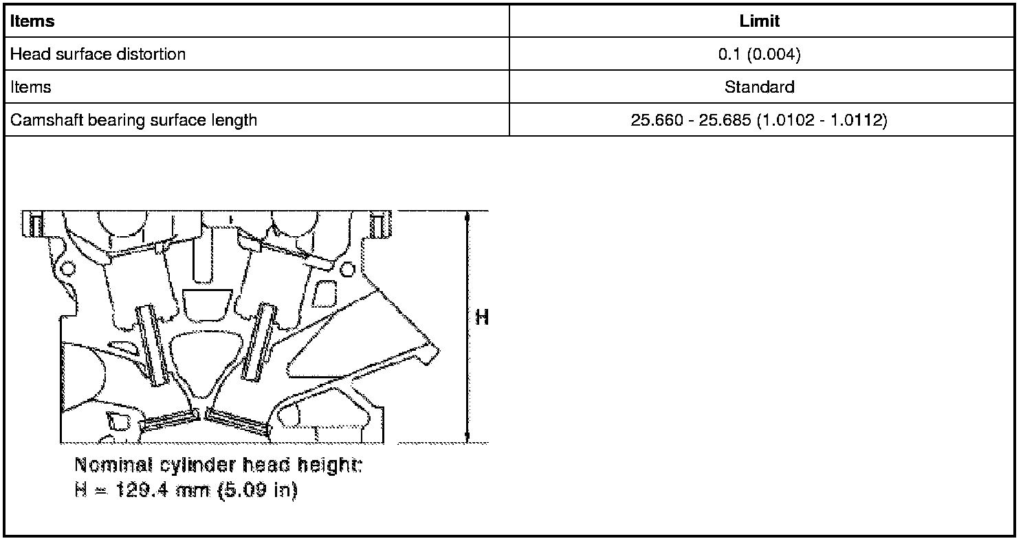
Cylinder Head
Unit: mm (in)
Valve
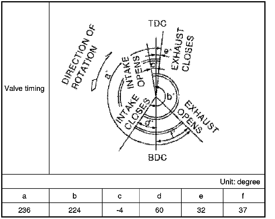
Valve Timing
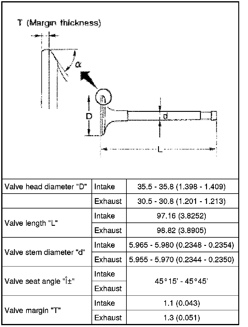
Valve Dimensions
Unit: mm (in)
Valve Clearance
Unit: mm (in)

*: Approximately 80°C (176°F)
Available Valve Lifter
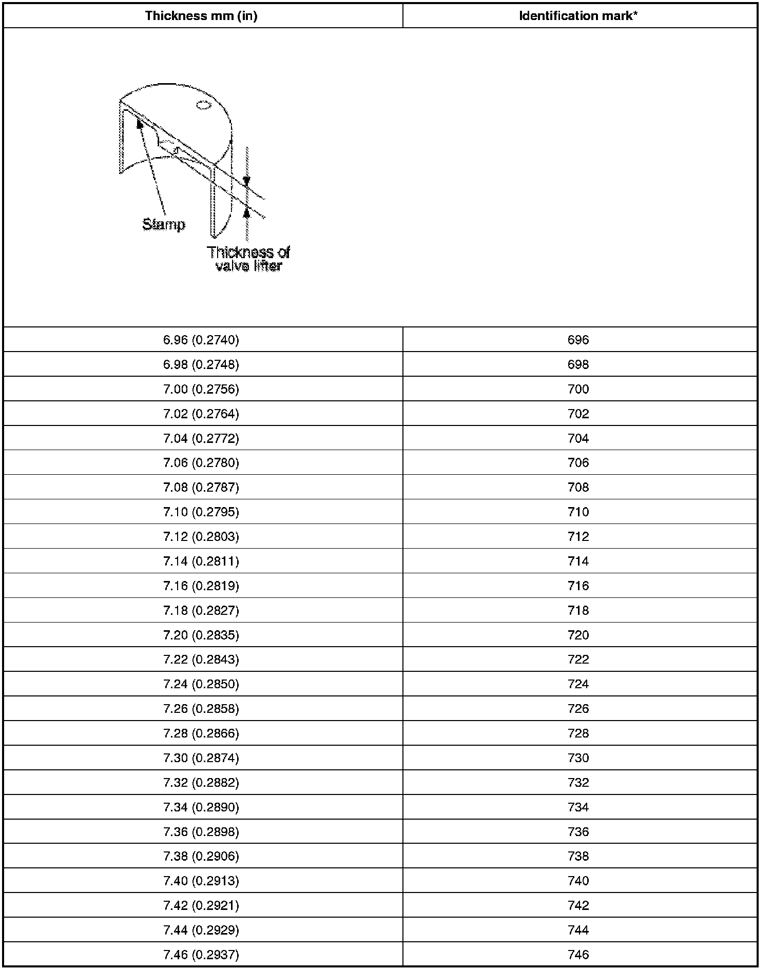
*: Always check with the Parts Department for the latest parts information
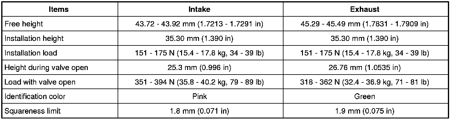
Valve Spring
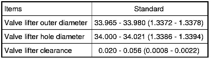
Valve Lifter
Unit: mm (in)
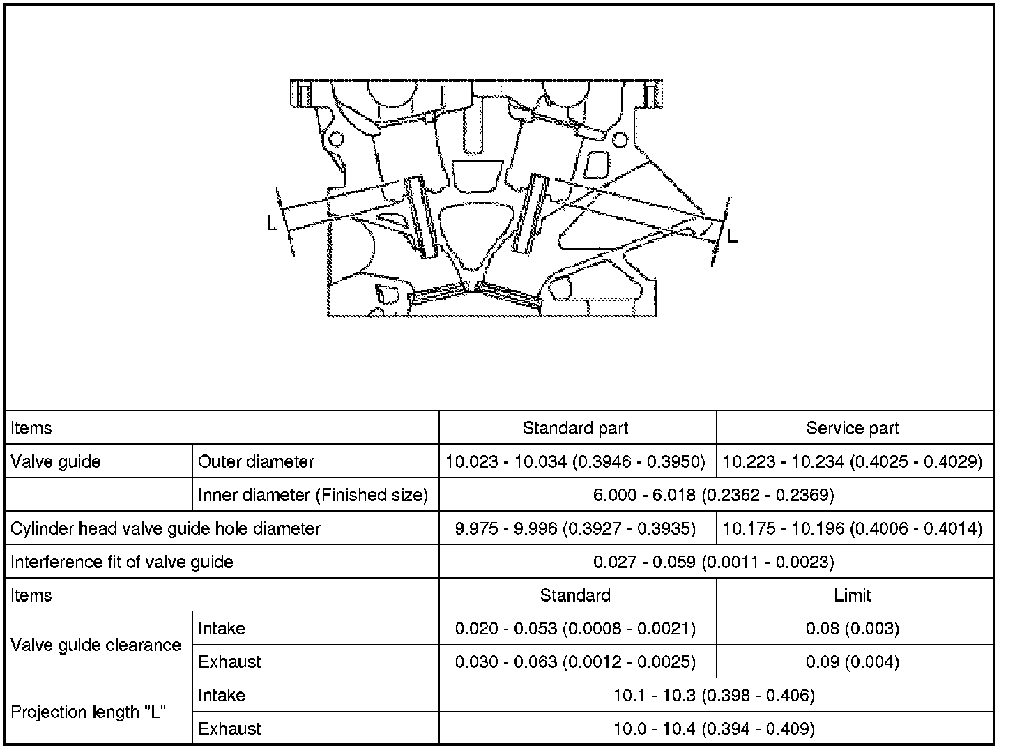
Valve Guide
Unit: mm (in)
Valve Seat
Unit: mm (in)
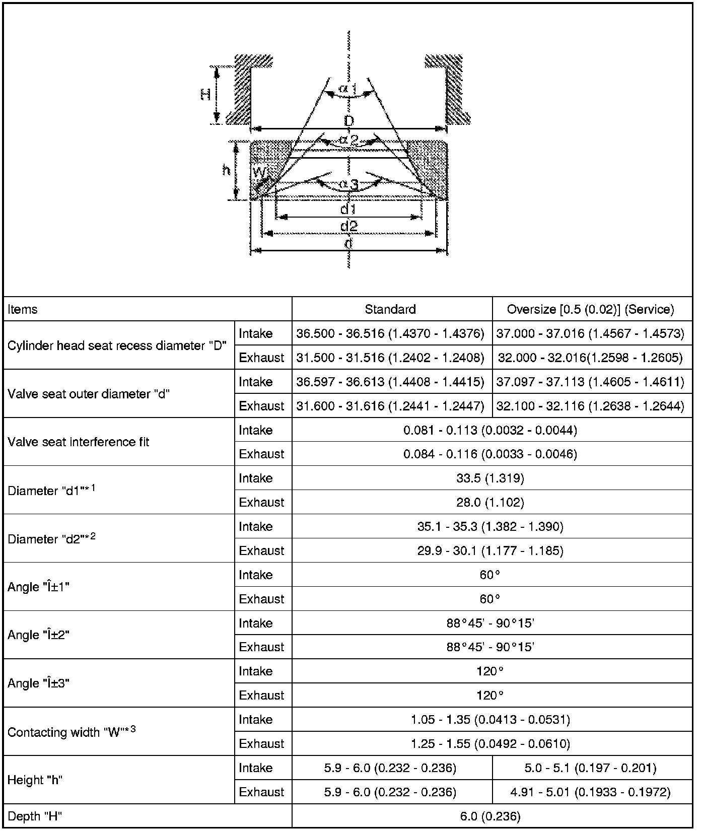
*1: Diameter made by intersection point of conic angles α1 and α2
*2: Diameter made by intersection point of conic angles α2 and α3
*3: Machining data
Valve Seal
Unit: mm (in)

Spark Plug Tube
Unit: mm (in)

Camshaft and Camshaft Bearing
Unit: mm (in)
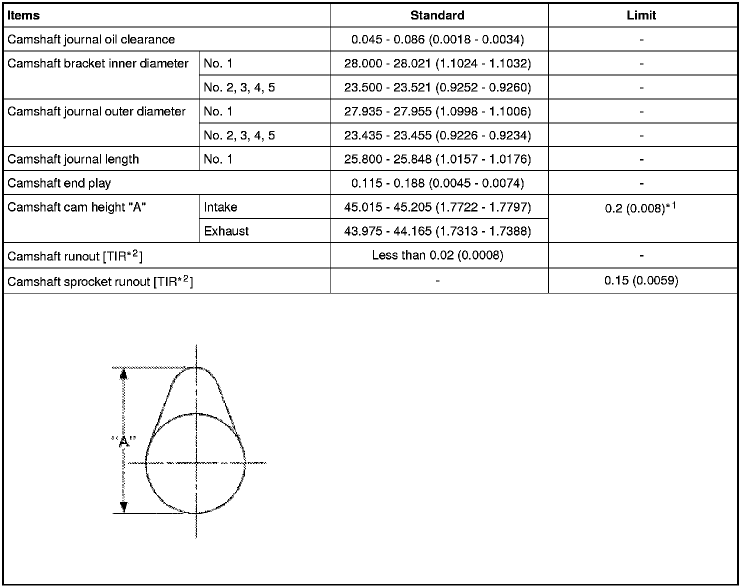
*1: Cam wear limit
*2: Total indicator reading
Cylinder Block
Unit: mm (in)
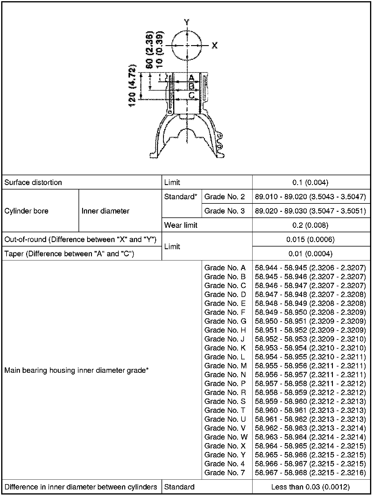
*:Always check with the Parts Department for the latest parts information.
Piston, Piston Ring and Piston Pin
Available Piston
Unit: mm (in)
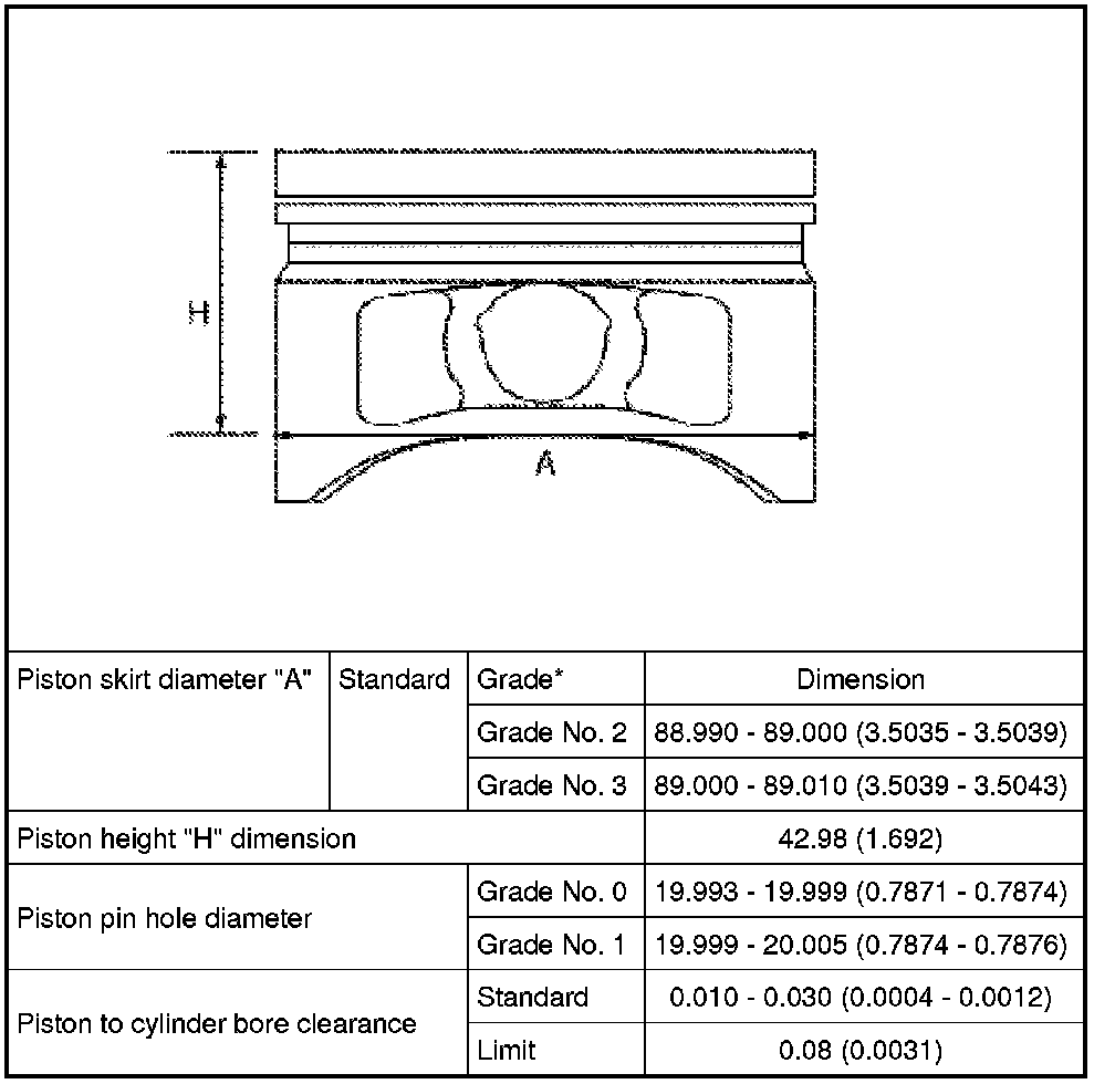
*: Always check with the Parts Department for the latest parts information
Piston Ring
Unit: mm (in)
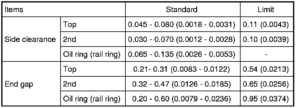
Piston Pin
Unit: mm (in)
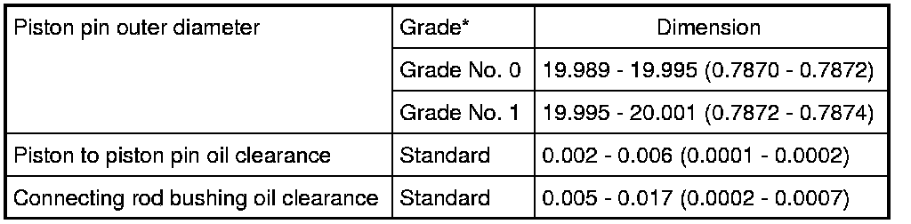
*: Always check with the Parts Department for the latest parts information
Connecting Rod
Unit: mm (in)
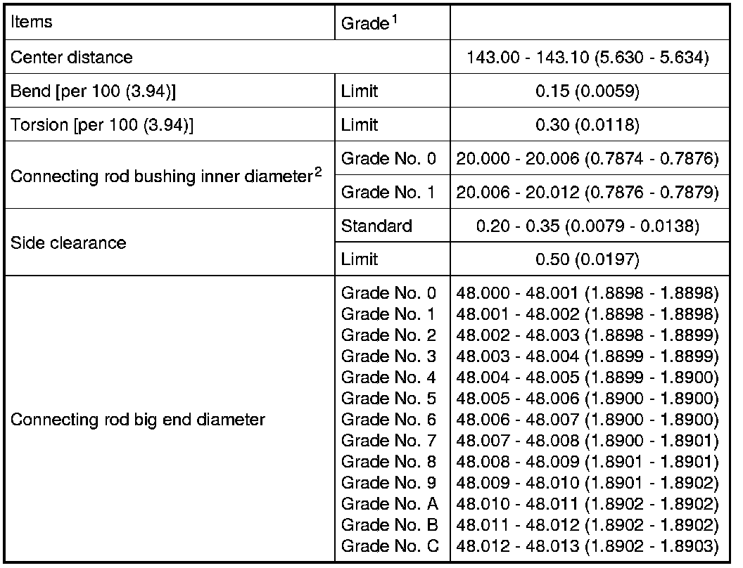
1: Always check with the Parts Department for the latest parts information
2: After installing in connecting rod
Crankshaft
Unit: mm (in)
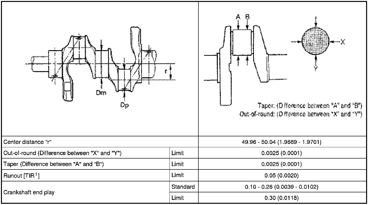
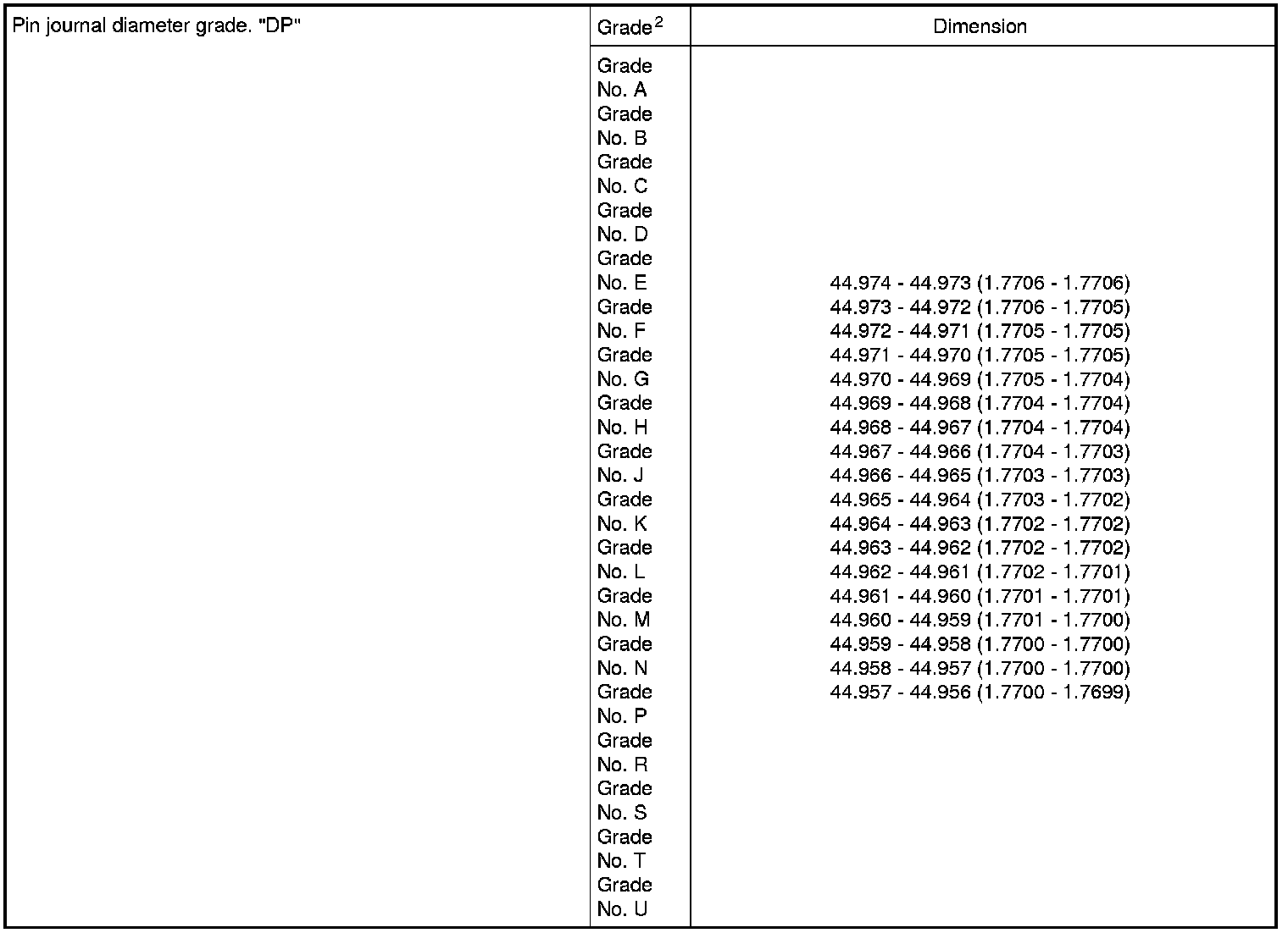
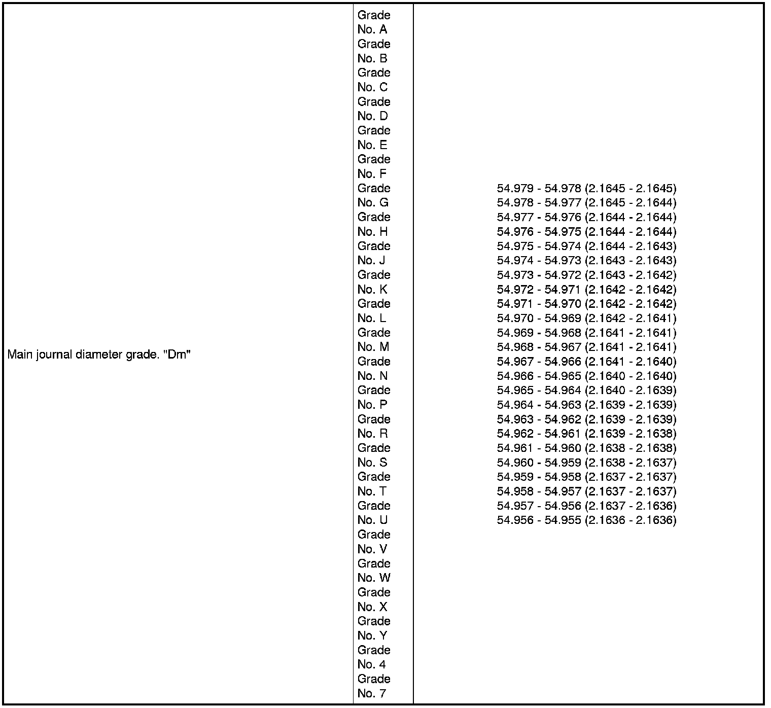
1: Total indicator reading
2: Always check with the Parts Department for the latest parts information
Main Bearing
Unit: mm (in)
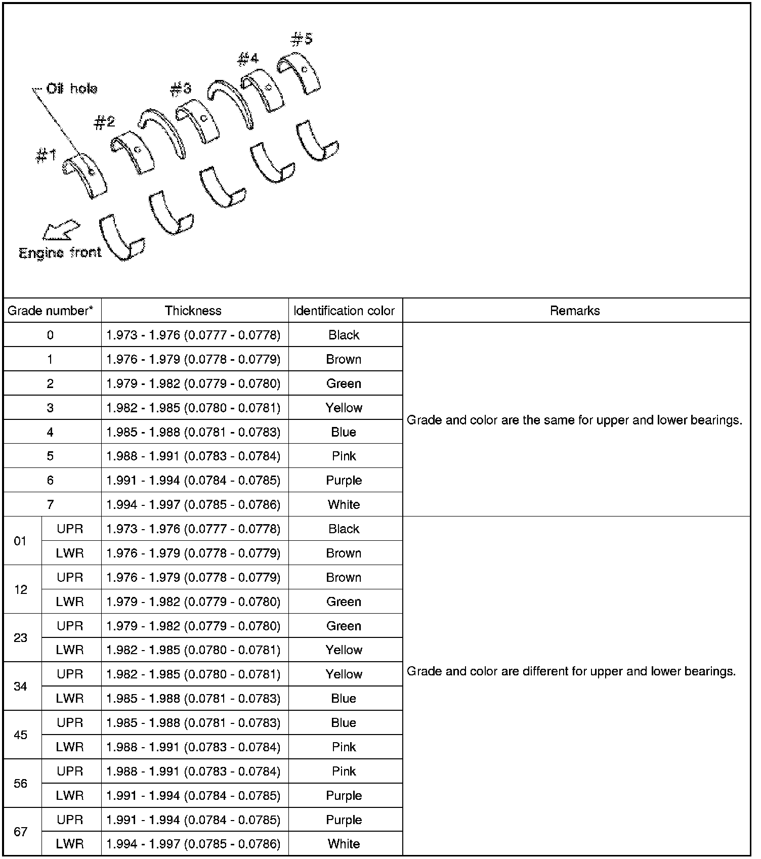
*: Always check with the Parts Department for the latest parts information
Undersize
Unit: mm (in)

Bearing Oil Clearance
Unit: mm (in)

Connecting Rod Bearing
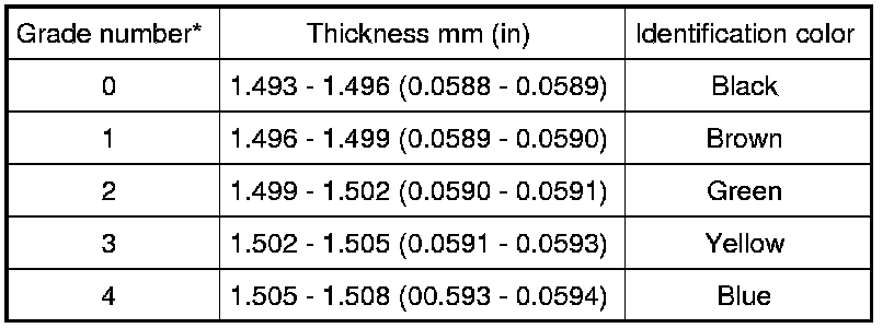
*: Always check with the Parts Department for the latest parts information
Undersize
Unit: mm (in)

Bearing Oil Clearance
Unit: mm (in)

Factory Service Tools
Use the Manual With the Right Hardware
Pair factory procedures with proven DIY tools so the instructions are easier to execute.
Disclosure: Verified tool recommendations may earn an affiliate commission at no cost to you.
When to See a Mechanic
Stop DIY work and contact a certified mechanic immediately if any of the following apply:
- • You smell fuel, burning insulation, or see smoke.
- • Brakes feel soft, pull hard to one side, or make grinding noises.
- • The engine overheats, stalls repeatedly, or misfires under load.
- • You are missing required tools, torque specs, or safe lifting equipment.
- • You are not confident in the next step or safety outcome.
Rather have a pro handle this?
A certified mobile mechanic comes to your home or office. They bring the tools, you stay comfortable. No tow truck, no waiting room, no surprises.
Comes to youSame-day available12-month warranty
Get a Free QuoteNo obligation. See pricing before you book.