
Safety Warning
DIY auto repair can cause serious injury, fire, or vehicle damage. These guides are for informational purposes only. Always follow OEM torque specs, wear PPE, and consult a certified mechanic if you are unsure. You are solely responsible for your safety.
2013 Subaru Outback F4-2.5L DOHCFACTORY OEM SERVICE PROCEDURE
Body Control Module: Service and Repair
Body Integrated Unit
NOTE
Refer to "Body Integrated Unit" for removal and installation procedure.
MT Gear Shift Lever
REMOVAL
1) Disconnect the ground cable from battery.
2) Lift up the vehicle.
3) Remove the center exhaust pipe.
4) Remove the heat shield cover.

5) Remove the plate cable assembly.

6) Remove the spring at the MT gear shift cable by expanding it and pulling down, and remove the MT gear shift cable from the gear shift lever assembly.
CAUTION:
Be careful not to deform the cable inner.

7) Remove the MT gear select cable from the gear shift lever assembly by pulling it in the direction of arrow in the figure.
CAUTION:
Be careful not to deform the cable inner.

8) Remove the cover cable assembly.

9) Lower the vehicle.
10) Remove the shift knob.
11) Remove the console front cover assembly and console box.
12) Remove the bolts, and then remove the gear shift lever assembly from the vehicle.
NOTE:
The MT gear shift lever cannot be disassembled.

INSTALLATION
1) Install the gear shift lever assembly.
Tightening torque:
18 Nm (1.8 kgf-m, 13.3 ft-lb)

2) Lift up the vehicle.
3) Install the cover cable assembly.
Tightening torque:
7.5 Nm (0.8 kgf-m, 5.5 ft-lb)

4) Connect the MT gear shift cable and MT gear select cable.
CAUTION:
^ Be careful not to deform the cable inner.
^ Do not twist the cable inner excessively.

5) Install the plate cable assembly.
Tightening torque:
7.5 Nm (0.8 kgf-m, 5.5 ft-lb)
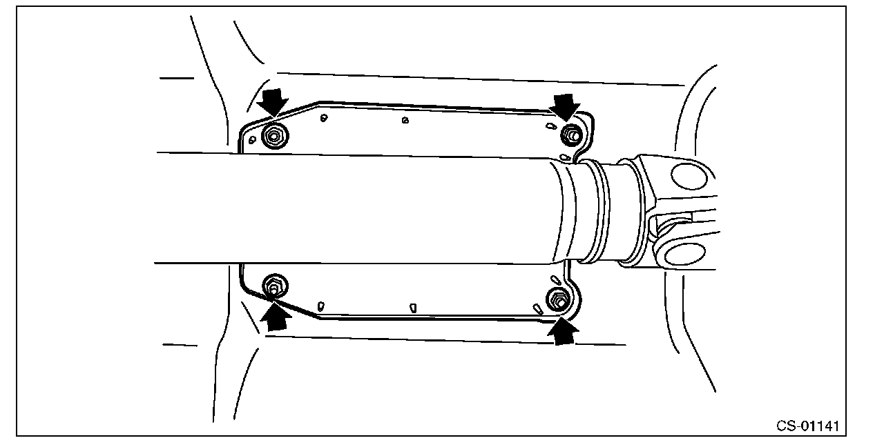
6) Install the heat shield cover.
Tightening torque:
18 Nm (1.8 kgf-m, 13.3 ft-lb)

7) Install the center exhaust pipe.
8) Lower the vehicle.
9) Adjust the detent of the MT gear shift lever.
10) Install the console front cover assembly and the console box.
11) Install the shift knob.
12) Make sure the gears can be shifted accurately into each gear. Adjust the MT gear select cable, if the gears cannot be shifted correctly.
INSPECTION
1) Check the parts for deformation, damage and wear. Repair or replace if necessary. Compare the removed parts with new parts to confirm if there are damages or not.
2) Check that selecting to the reverse direction is disable unless the slider is pulled up.
3) Check that selecting to the reverse direction is possible when the slider is pulled up to the full.
4) Check that the shift lever moves to initial position, when the slider backs to the neutral position from step 3).

ADJUSTMENT
NOTE:
Adjust the detent when the following items have been replaced.
^ MT gear shift lever
^ MT gear select cable
^ Manual transmission assembly
1) Remove the shift knob.
2) Remove the console front cover assembly.
3) Place the shift lever in neutral position.
4) Loosen the detent bolt.
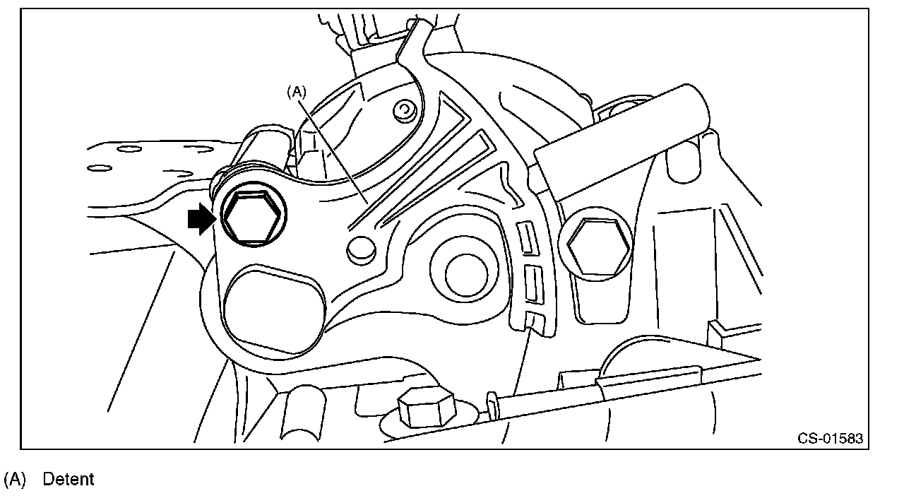
5) Move the detent up and down and align the detent pin to the groove. Make sure that the detent pin is fitted in the groove and a clicking sound is heard.

6) Pull up the slider, select the shift lever to the reverse direction, and make sure it returns to the neutral position after releasing hands.
7) Tighten the detent bolt.
NOTE:
When tightening the bolt, hold the shift lever by hand so that the detent pin does not come out from the groove.
Tightening torque:
7.5 Nm (0.8 kgf-m, 5.5 ft-lb)

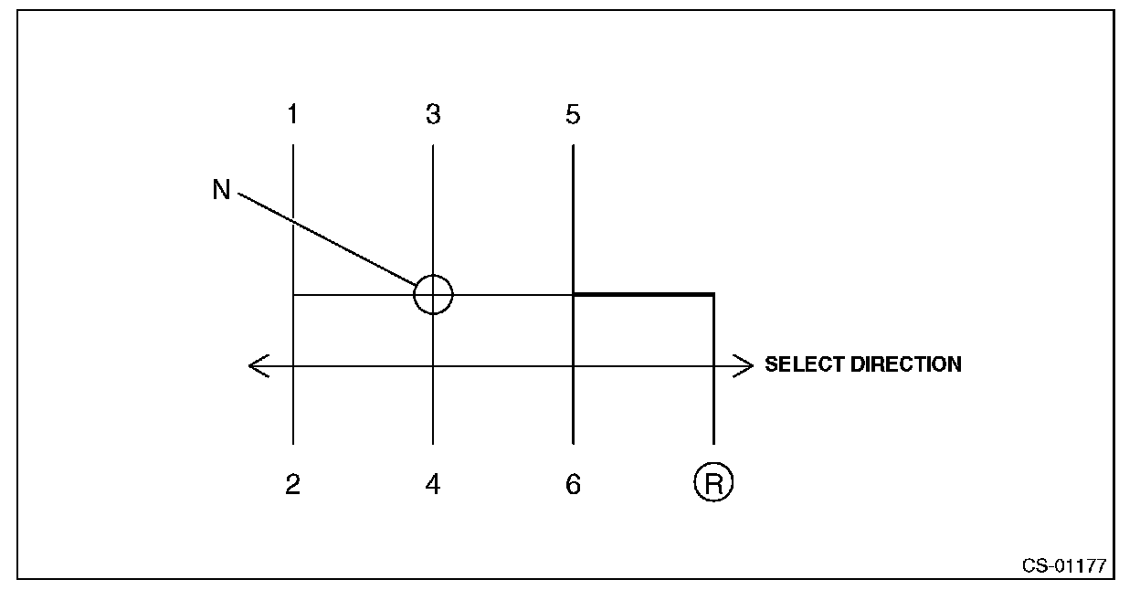
8) Move the shift lever to the neutral position, and check that the play in the select direction above the shift knob is within the reference standard. If it is not within the reference standard, repeat adjustment procedures from the beginning.
Play in neutral position:
Reference standard
1.5 mm (0.059 in) or less
NOTE
Refer to "Body Integrated Unit" for removal and installation procedure.
MT Gear Shift Lever
REMOVAL
1) Disconnect the ground cable from battery.
2) Lift up the vehicle.
3) Remove the center exhaust pipe.
4) Remove the heat shield cover.
5) Remove the plate cable assembly.
6) Remove the spring at the MT gear shift cable by expanding it and pulling down, and remove the MT gear shift cable from the gear shift lever assembly.
CAUTION:
Be careful not to deform the cable inner.
7) Remove the MT gear select cable from the gear shift lever assembly by pulling it in the direction of arrow in the figure.
CAUTION:
Be careful not to deform the cable inner.
8) Remove the cover cable assembly.
9) Lower the vehicle.
10) Remove the shift knob.
11) Remove the console front cover assembly and console box.
12) Remove the bolts, and then remove the gear shift lever assembly from the vehicle.
NOTE:
The MT gear shift lever cannot be disassembled.
INSTALLATION
1) Install the gear shift lever assembly.
Tightening torque:
18 Nm (1.8 kgf-m, 13.3 ft-lb)
2) Lift up the vehicle.
3) Install the cover cable assembly.
Tightening torque:
7.5 Nm (0.8 kgf-m, 5.5 ft-lb)
4) Connect the MT gear shift cable and MT gear select cable.
CAUTION:
^ Be careful not to deform the cable inner.
^ Do not twist the cable inner excessively.
5) Install the plate cable assembly.
Tightening torque:
7.5 Nm (0.8 kgf-m, 5.5 ft-lb)
6) Install the heat shield cover.
Tightening torque:
18 Nm (1.8 kgf-m, 13.3 ft-lb)
7) Install the center exhaust pipe.
8) Lower the vehicle.
9) Adjust the detent of the MT gear shift lever.
10) Install the console front cover assembly and the console box.
11) Install the shift knob.
12) Make sure the gears can be shifted accurately into each gear. Adjust the MT gear select cable, if the gears cannot be shifted correctly.
INSPECTION
1) Check the parts for deformation, damage and wear. Repair or replace if necessary. Compare the removed parts with new parts to confirm if there are damages or not.
2) Check that selecting to the reverse direction is disable unless the slider is pulled up.
3) Check that selecting to the reverse direction is possible when the slider is pulled up to the full.
4) Check that the shift lever moves to initial position, when the slider backs to the neutral position from step 3).
ADJUSTMENT
NOTE:
Adjust the detent when the following items have been replaced.
^ MT gear shift lever
^ MT gear select cable
^ Manual transmission assembly
1) Remove the shift knob.
2) Remove the console front cover assembly.
3) Place the shift lever in neutral position.
4) Loosen the detent bolt.
5) Move the detent up and down and align the detent pin to the groove. Make sure that the detent pin is fitted in the groove and a clicking sound is heard.
6) Pull up the slider, select the shift lever to the reverse direction, and make sure it returns to the neutral position after releasing hands.
7) Tighten the detent bolt.
NOTE:
When tightening the bolt, hold the shift lever by hand so that the detent pin does not come out from the groove.
Tightening torque:
7.5 Nm (0.8 kgf-m, 5.5 ft-lb)
8) Move the shift lever to the neutral position, and check that the play in the select direction above the shift knob is within the reference standard. If it is not within the reference standard, repeat adjustment procedures from the beginning.
Play in neutral position:
Reference standard
1.5 mm (0.059 in) or less
Factory Service Tools
Use the Manual With the Right Hardware
Pair factory procedures with proven DIY tools so the instructions are easier to execute.
Disclosure: Verified tool recommendations may earn an affiliate commission at no cost to you.
When to See a Mechanic
Stop DIY work and contact a certified mechanic immediately if any of the following apply:
- • You smell fuel, burning insulation, or see smoke.
- • Brakes feel soft, pull hard to one side, or make grinding noises.
- • The engine overheats, stalls repeatedly, or misfires under load.
- • You are missing required tools, torque specs, or safe lifting equipment.
- • You are not confident in the next step or safety outcome.
Rather have a pro handle this?
A certified mobile mechanic comes to your home or office. They bring the tools, you stay comfortable. No tow truck, no waiting room, no surprises.
Comes to youSame-day available12-month warranty
Get a Free QuoteNo obligation. See pricing before you book.