
Safety Warning
DIY auto repair can cause serious injury, fire, or vehicle damage. These guides are for informational purposes only. Always follow OEM torque specs, wear PPE, and consult a certified mechanic if you are unsure. You are solely responsible for your safety.
2010 Subaru Outback F4-2.5L SOHCFACTORY OEM SERVICE PROCEDURE
Subframe: Service and Repair
Cradle
REMOVAL
1) Set the vehicle on a lift.
2) Position the tilt position of the steering column to the lowest position, and lock the tilt lever.
3) Prevent the steering wheel from turning using the seat belt.
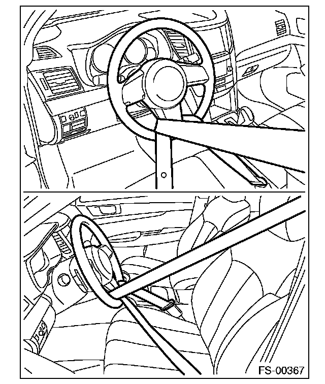
4) Remove the front wheels.
5) Disconnect the ground cable from battery.
6) Remove the air intake duct.
7) Remove the air intake boot assembly. (non-turbo model)
8) Remove the intercooler and the intercooler stay. (turbo model)
9) Remove the clips and remove the grille bracket.
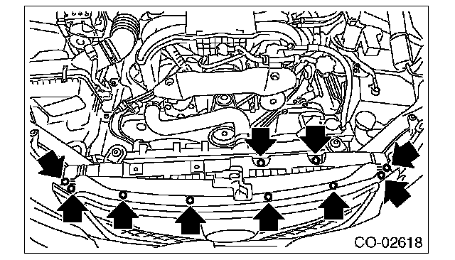
10) Remove the power steering hose bracket and power steering hose.
1) Remove the clip and disconnect the hose from the pipe.
2) Remove the power steering hose bracket.
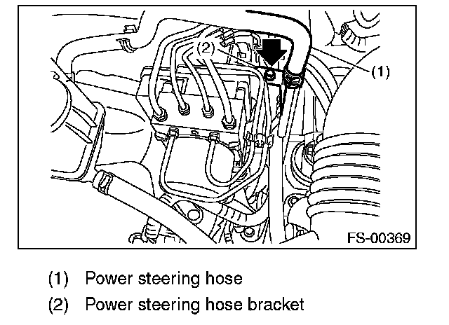
3) Remove the hose from the power steering PUMP.
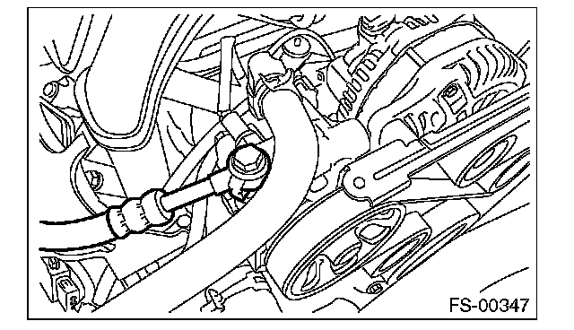
NOTE:
Plug the holes to prevent foreign objects from entering the removed hose and pipe.
11) Remove the throttle body from the intake manifold.
NOTE:
Do not disconnect the inlet and outlet hoses of engine coolant.
12) Replace the engine hanger installed on the engine with the SUBARU genuine engine hanger (H4 non-turbo model) or ST (H6 model).
Tightening torque:
16 Nm (1.6 kgf-m, 11.8 ft-lb)
- H4 non-turbo model
SUBARU genuine part
10004AA180 HANGER CP ENGINE RR
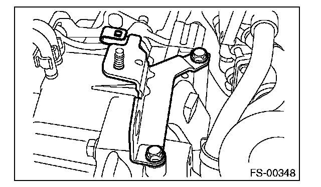
- H6 model
ST 18360AA020 HANGER

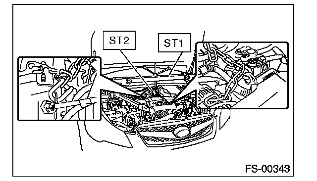
13) Hang the engine using ST, chain sling and shackle.
1) Set the ST on the vehicle.
ST1 99099AJ000 ENGINE HANGER
ST2 99099AJ010 CHAIN BALANCER
CAUTION:
Set the arms of ST (ENGINE HANGER) at the locations shown in the figure.

2) Attach the shackle to the both ends of chain sling.
3) Pass the chain sling through the CHAIN BALANCER and secure the both ends to the hooks on the engine.
CAUTION:
- Set the chain sling so that it does not contact the engine parts.
- Use a chain sling with the diameter of 6 mm (0.24 in) or 6.3 mm (0.25 in), the length of 0.8 - 1 m (2.6 - 3.3 ft), the chain inner width of 8.5 mm (0.33 in) or more, the chain outer width of 23.5 mm (0.93 in) or less and the load capacity of 1.2 t (2646 lb) or more.

- Use a shackle with the load capacity of 250 kg (551 lb) or more.

14) Remove the nuts connecting the main mount and the transmission mounting bracket.

15) Remove the universal joint.
16) Remove the front exhaust pipe.
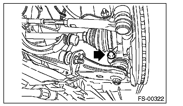
17) Disconnect the front arm.
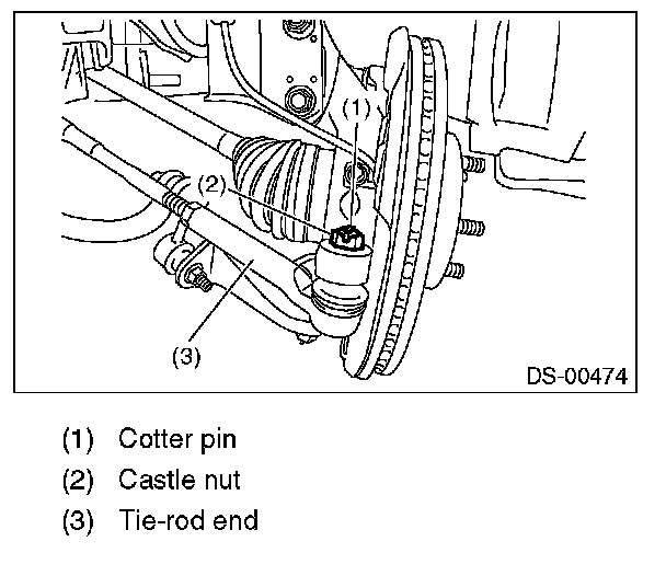
18) Disconnect the tie-rod end.
19) Attach the sling belt so that it wraps around the both frames using the shackle.
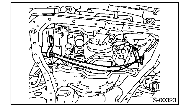
CAUTION:
- Be sure to attach the sling belt to ensure safety in operation.
- Use a sling belt with the length of 2 m (6.6 ft), the width of 35 - 40 mm (1.38 - 1.57 in) and the load capacity of 1 t (2205 lb) or more.
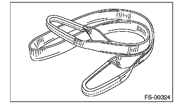
- Use a shackle with the load capacity of 0.5 t (1103 lb) or more.

20) Remove the bolt on the front cushion rubber.
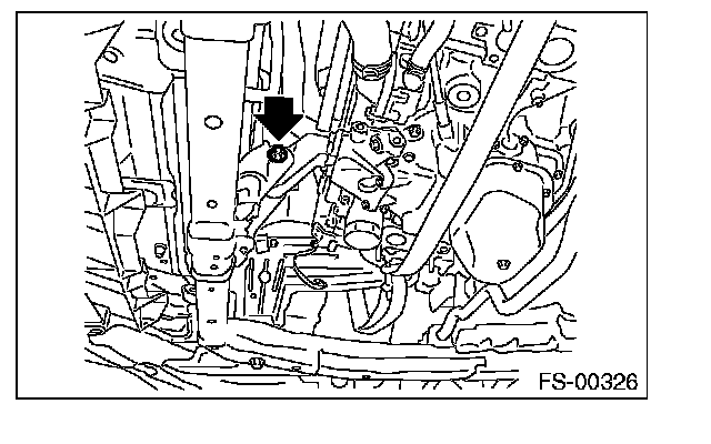
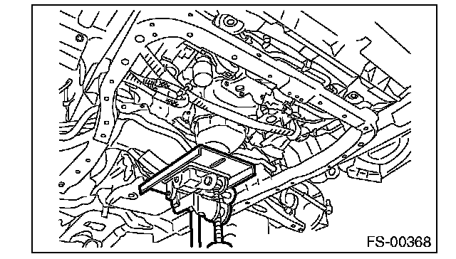
21) Support the cradle with a transmission jack and remove the bolts and nuts.
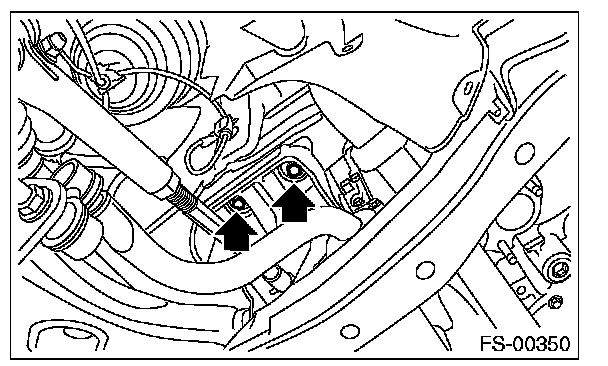
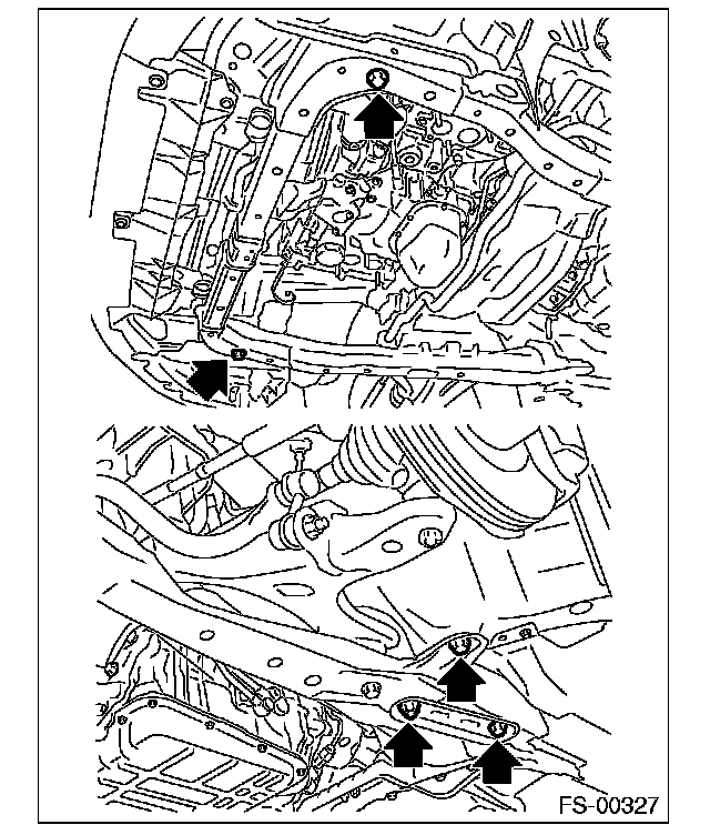
22) Remove the cradle from the vehicle.
CAUTION:
The cradle is heavy. Remove it carefully by paying attention to the balance.
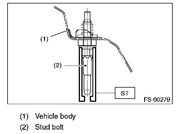
23) To remove the stud bolt, use the ST.
ST 20299AG020 STUD BOLT SOCKET
CAUTION:
Do not remove the stud bolt unnecessarily. Always replace the parts with new parts when removed.
INSTALLATION
1) Install in the reverse order of removal.
NOTE:
Replace the gasket of the throttle body with a new gasket.
CAUTION:
- Use a new bolt and self-locking nut.
- Perform installation of the universal joint when the tilt position of the steering column is at the lowest position.
- Tighten the bolts of the universal joint in the order of gearbox side and column shaft side.
2) Inspect the wheel alignment and adjust if necessary.
REMOVAL
1) Set the vehicle on a lift.
2) Position the tilt position of the steering column to the lowest position, and lock the tilt lever.
3) Prevent the steering wheel from turning using the seat belt.
4) Remove the front wheels.
5) Disconnect the ground cable from battery.
6) Remove the air intake duct.
7) Remove the air intake boot assembly. (non-turbo model)
8) Remove the intercooler and the intercooler stay. (turbo model)
9) Remove the clips and remove the grille bracket.
10) Remove the power steering hose bracket and power steering hose.
1) Remove the clip and disconnect the hose from the pipe.
2) Remove the power steering hose bracket.
3) Remove the hose from the power steering PUMP.
NOTE:
Plug the holes to prevent foreign objects from entering the removed hose and pipe.
11) Remove the throttle body from the intake manifold.
NOTE:
Do not disconnect the inlet and outlet hoses of engine coolant.
12) Replace the engine hanger installed on the engine with the SUBARU genuine engine hanger (H4 non-turbo model) or ST (H6 model).
Tightening torque:
16 Nm (1.6 kgf-m, 11.8 ft-lb)
- H4 non-turbo model
SUBARU genuine part
10004AA180 HANGER CP ENGINE RR
- H6 model
ST 18360AA020 HANGER
13) Hang the engine using ST, chain sling and shackle.
1) Set the ST on the vehicle.
ST1 99099AJ000 ENGINE HANGER
ST2 99099AJ010 CHAIN BALANCER
CAUTION:
Set the arms of ST (ENGINE HANGER) at the locations shown in the figure.
2) Attach the shackle to the both ends of chain sling.
3) Pass the chain sling through the CHAIN BALANCER and secure the both ends to the hooks on the engine.
CAUTION:
- Set the chain sling so that it does not contact the engine parts.
- Use a chain sling with the diameter of 6 mm (0.24 in) or 6.3 mm (0.25 in), the length of 0.8 - 1 m (2.6 - 3.3 ft), the chain inner width of 8.5 mm (0.33 in) or more, the chain outer width of 23.5 mm (0.93 in) or less and the load capacity of 1.2 t (2646 lb) or more.
- Use a shackle with the load capacity of 250 kg (551 lb) or more.
14) Remove the nuts connecting the main mount and the transmission mounting bracket.
15) Remove the universal joint.
16) Remove the front exhaust pipe.
17) Disconnect the front arm.
18) Disconnect the tie-rod end.
19) Attach the sling belt so that it wraps around the both frames using the shackle.
CAUTION:
- Be sure to attach the sling belt to ensure safety in operation.
- Use a sling belt with the length of 2 m (6.6 ft), the width of 35 - 40 mm (1.38 - 1.57 in) and the load capacity of 1 t (2205 lb) or more.
- Use a shackle with the load capacity of 0.5 t (1103 lb) or more.
20) Remove the bolt on the front cushion rubber.
21) Support the cradle with a transmission jack and remove the bolts and nuts.
22) Remove the cradle from the vehicle.
CAUTION:
The cradle is heavy. Remove it carefully by paying attention to the balance.
23) To remove the stud bolt, use the ST.
ST 20299AG020 STUD BOLT SOCKET
CAUTION:
Do not remove the stud bolt unnecessarily. Always replace the parts with new parts when removed.
INSTALLATION
1) Install in the reverse order of removal.
NOTE:
Replace the gasket of the throttle body with a new gasket.
CAUTION:
- Use a new bolt and self-locking nut.
- Perform installation of the universal joint when the tilt position of the steering column is at the lowest position.
- Tighten the bolts of the universal joint in the order of gearbox side and column shaft side.
2) Inspect the wheel alignment and adjust if necessary.
Factory Service Tools
Use the Manual With the Right Hardware
Pair factory procedures with proven DIY tools so the instructions are easier to execute.
Disclosure: Verified tool recommendations may earn an affiliate commission at no cost to you.
When to See a Mechanic
Stop DIY work and contact a certified mechanic immediately if any of the following apply:
- • You smell fuel, burning insulation, or see smoke.
- • Brakes feel soft, pull hard to one side, or make grinding noises.
- • The engine overheats, stalls repeatedly, or misfires under load.
- • You are missing required tools, torque specs, or safe lifting equipment.
- • You are not confident in the next step or safety outcome.