
Safety Warning
DIY auto repair can cause serious injury, fire, or vehicle damage. These guides are for informational purposes only. Always follow OEM torque specs, wear PPE, and consult a certified mechanic if you are unsure. You are solely responsible for your safety.
2003 Subaru Outback F6-3.0LFACTORY OEM SERVICE PROCEDURE
Alternator: Testing and Inspection
INSPECTION
DIODE
CAUTION: Never use a mega tester (measuring use for high voltage) or any other similar measure for this test; otherwise, the diodes may be damaged.

1. Checking positive diode
Check for continuity between the diode lead and positive side heat sink. The positive diode is in good condition if resistance is 1 Ohm or less only in the direction from the diode lead to heat sink.

2. Checking negative diode
Check for continuity between the negative side heat sink and diode lead. The negative diode is in good condition if resistance is 1 Ohm or less only in the direction from the heat sink to diode lead.
ROTOR
1. Slip ring surface
Inspect the slip rings for contamination or any roughness of the sliding surface. Repair the slip ring surface using a lathe or sand paper.
2. Slip ring outer diameter
Measure the slip ring outer diameter. If the slip ring is worn replace rotor assembly.
Slip ring outer diameter:
Standard 22.7 mm (0.894 in)
Limit 22.1 mm (0.870 in)

3. Continuity test
Check the resistance between slip rings using circuit tester.
If the resistance is not within specification, replace the rotor assembly.
Specified resistance: Approx. 2.0 - 2.4 Ohm

4. Insulation test
Check the continuity between slip ring and rotor core or shaft. If resistance is 1 Ohm or less, the rotor coil is grounded, and so replace the rotor assembly.
5. Ball bearing (rear side)
Check the rear ball bearing. Replace if it is noisy or if the rotor does not turn smoothly.
STATOR

1. Continuity test
Inspect the stator coil for continuity between each end of the lead wires. If resistance is 1 MOhm or more, the lead wire is broken, and so replace the stator assembly.

2. Insulation test
Inspect the stator coil for continuity between stator core and each end of lead wire. If resistance is 1 Ohm or less, the stator coil is grounded, and so replace the stator assembly.
BRUSH

1. Measure the length of each brush. If wear exceeds the service limit, replace the brush. Each brush has the service limit mark (A) on it.
Brush length:
Standard 18.5 mm (0.728 in)
Service limit 5.0 mm (0.197 in)
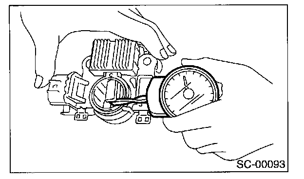
2. Checking brush spring for proper pressure Using a spring pressure indicator, push the brush into the brush holder until its tip protrudes 2 mm (0.08 in). Then measure the pressure of brush spring. If the pressure is less than 2.2 N (224 g, 7.91 oz), replace the brush spring with a new one. The new spring must have a pressure of 4.8 to 6.0 N (489 to 612 g, 17.26 to 21.60 oz).
BEARING (FRONT SIDE)
Check the front ball bearing. If the resistance is felt while rotating, or if abnormal noise is heard, replace the ball bearing.
DIODE
CAUTION: Never use a mega tester (measuring use for high voltage) or any other similar measure for this test; otherwise, the diodes may be damaged.
1. Checking positive diode
Check for continuity between the diode lead and positive side heat sink. The positive diode is in good condition if resistance is 1 Ohm or less only in the direction from the diode lead to heat sink.
2. Checking negative diode
Check for continuity between the negative side heat sink and diode lead. The negative diode is in good condition if resistance is 1 Ohm or less only in the direction from the heat sink to diode lead.
ROTOR
1. Slip ring surface
Inspect the slip rings for contamination or any roughness of the sliding surface. Repair the slip ring surface using a lathe or sand paper.
2. Slip ring outer diameter
Measure the slip ring outer diameter. If the slip ring is worn replace rotor assembly.
Slip ring outer diameter:
Standard 22.7 mm (0.894 in)
Limit 22.1 mm (0.870 in)
3. Continuity test
Check the resistance between slip rings using circuit tester.
If the resistance is not within specification, replace the rotor assembly.
Specified resistance: Approx. 2.0 - 2.4 Ohm
4. Insulation test
Check the continuity between slip ring and rotor core or shaft. If resistance is 1 Ohm or less, the rotor coil is grounded, and so replace the rotor assembly.
5. Ball bearing (rear side)
Check the rear ball bearing. Replace if it is noisy or if the rotor does not turn smoothly.
STATOR
1. Continuity test
Inspect the stator coil for continuity between each end of the lead wires. If resistance is 1 MOhm or more, the lead wire is broken, and so replace the stator assembly.
2. Insulation test
Inspect the stator coil for continuity between stator core and each end of lead wire. If resistance is 1 Ohm or less, the stator coil is grounded, and so replace the stator assembly.
BRUSH
1. Measure the length of each brush. If wear exceeds the service limit, replace the brush. Each brush has the service limit mark (A) on it.
Brush length:
Standard 18.5 mm (0.728 in)
Service limit 5.0 mm (0.197 in)
2. Checking brush spring for proper pressure Using a spring pressure indicator, push the brush into the brush holder until its tip protrudes 2 mm (0.08 in). Then measure the pressure of brush spring. If the pressure is less than 2.2 N (224 g, 7.91 oz), replace the brush spring with a new one. The new spring must have a pressure of 4.8 to 6.0 N (489 to 612 g, 17.26 to 21.60 oz).
BEARING (FRONT SIDE)
Check the front ball bearing. If the resistance is felt while rotating, or if abnormal noise is heard, replace the ball bearing.
Factory Service Tools
Use the Manual With the Right Hardware
Pair factory procedures with proven DIY tools so the instructions are easier to execute.
Disclosure: Verified tool recommendations may earn an affiliate commission at no cost to you.
When to See a Mechanic
Stop DIY work and contact a certified mechanic immediately if any of the following apply:
- • You smell fuel, burning insulation, or see smoke.
- • Brakes feel soft, pull hard to one side, or make grinding noises.
- • The engine overheats, stalls repeatedly, or misfires under load.
- • You are missing required tools, torque specs, or safe lifting equipment.
- • You are not confident in the next step or safety outcome.