
Safety Warning
DIY auto repair can cause serious injury, fire, or vehicle damage. These guides are for informational purposes only. Always follow OEM torque specs, wear PPE, and consult a certified mechanic if you are unsure. You are solely responsible for your safety.
2003 Subaru Outback F6-3.0LFACTORY OEM SERVICE PROCEDURE
Timing Chain Assembly
REMOVAL
1) Remove crankshaft pulley.
2) Remove front chain cover.
3) Remove chain tensioner (RH).

NOTE: Make sure plunger (A) does not come out.
4) Remove chain guide. (Right-hand between cams)
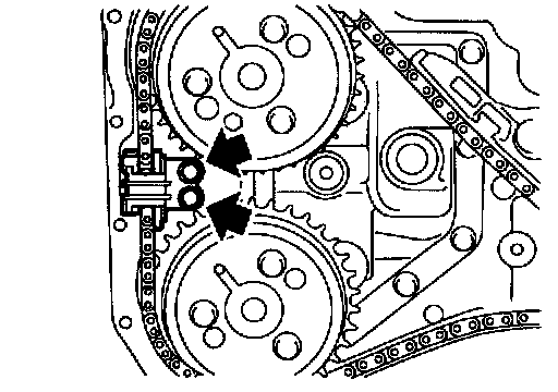
5) Remove chain guide (RH).

6) Remove chain tensioner lever (RH).
(A) Chain guide (RH)
(B) Chain tensioner lever (RH)
7) Remove timing chain (RH).
8) Remove chain tensioner (LH).
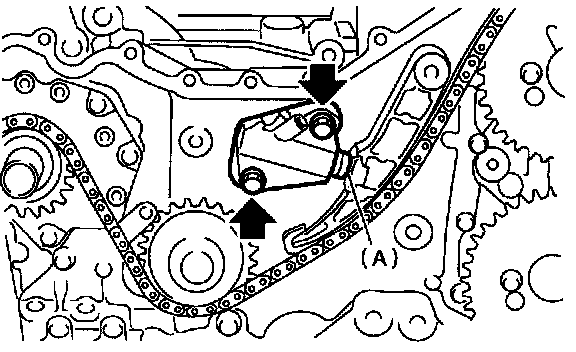
NOTE: Make sure plunger (A) does not come out.
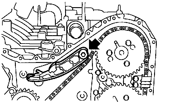
9) Remove chain tensioner lever (LH).

Remove chain guide. (Left-hand between cams)

10) Remove chain guide (LH).

11) Remove chain guide. (Center)
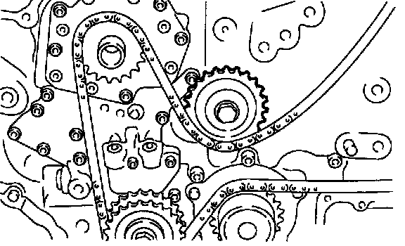
12) Remove idler sprocket. (Upper)
13) Remove timing chain (LH).

14) Remove idler sprocket. (Lower)
B: INSTALLATION
CAUTION:
- During installation, be careful to prevent foreign objects from attaching to or mixing with assembled components.
- Apply engine oil to chain guide, chain tensioner lever, and idler sprocket during installation.
1) Preparation for installation of chain tensioner.
(1) Put the screw, spring, pin and tension rod into the tensioner body.
(2) While pressing tensioner onto rubber mat, twist it left and right to shorten tension rod. Then set a thin pin into the holes between tension rod and tensioner body to hold it.

NOTE: Carry out the work on rubber mat or other nonslip material.
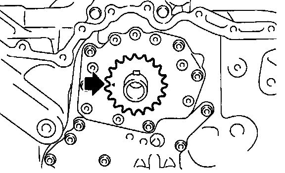
2) Using ST, align "top mark" on crankshaft sprocket at 9 o'clock position as shown in the figure.

3) Using ST, align four key grooves on camshaft sprocket at 12 O'clock position as shown in the figure.

4) Rotate crankshaft sprocket clockwise to align "top mark" at 12 o'clock position as shown in the figure. (Piston # 1 is at TDC.)
CAUTION: Do not rotate crankshaft and camshaft sprockets until timing chain is completely routed.
5) Install the idler sprocket. (Lower)
Tightening torque: 69 N.m (7.0 kgf-m, 50.6 ft-lb)
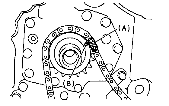
(A) Gold
6) Install timing chain LH.
(1) Align the timing mark (B) on crankshaft sprocket with the matching mark (A) on timing chain LH.
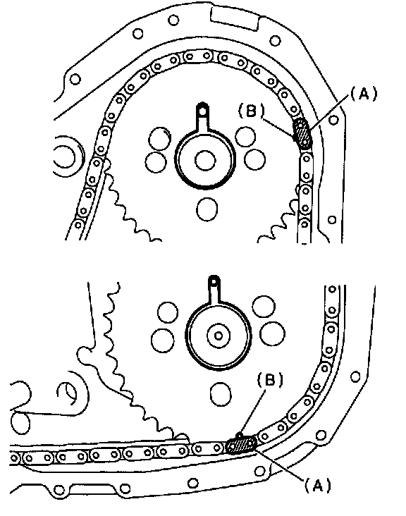
(A) Dark gray
(2) Route timing chain LH on idler sprocket (Lower), water pump, exhaust cam sprocket, and intake cam sprocket in order.
CAUTION: Check that matching marks on camshaft sprocket and timing chain are aligned, same as crankshaft sprocket.
(3) Install chain idler. (Upper)
Tightening torque: 69 N.m (7.0 kgf-m, 50.6 ft lb)
(4) Install chain guide. (Left-hand between cams)
Tightening torque: 6.3 N.m (0.64 kgf-m, 4.6 ft-lb)
(5) Install chain guide (LH).
Tightening torque: 16 N.m (1.6 kgf-m, 11.6 ft-lb)
(6) Install chain tensioner lever LH.
Tightening torque: 16 N.m (1.6 kgf-m, 11.6 ft-lb)

(7) Install chain tensioner LH.
Tightening torque: 16 N.m (1.6 kgf-m, 11.6 ft-lb)

8) Install timing chain RH.
(1) On idler sprocket (Lower) , align matching marks on timing chains LH and RH.
(A) Lower idler sprocket
(B) Timing chain RH
(C) Timing chain LH
(D) Dark gray
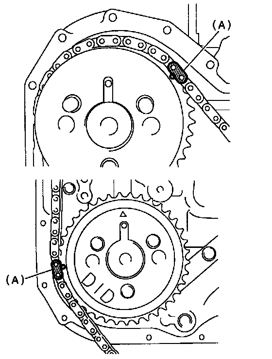
(A) Gold
(2) Route timing chain RH on intake cam sprocket and then exhaust cam sprocket.
CAUTION: Check that matching marks on camshaft sprocket and timing chain are aligned, same as LH side.
(3) Install chain guide (RH).
(4) Install chain tensioner lever (RH).
Tightening torque: 16 N.m (1.6 kgf-m, 11.6 ft-lb)
(1) Chain guide (RH)
(2) Chain tensioner lever (RH)
(5) Install timing chain guide RH No.1.
Tightening torque: 6.3 N.m (0.64 kgf-m, 4.6 ft-lb)
(6) Install the chain tensioner (RH).
Tightening torque: 16 N.m (1.6 kgf-m, 11.6 ft-lb)
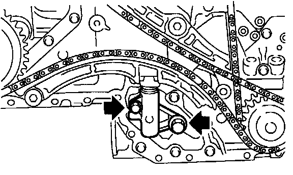
(7) Adjust the clearance between chain guide (RH) and chain guide (Center) to the range between 8.4 mm (0.331 in) to 8.6 mm (0.339 in). And install chain guide (Center).
Tightening torque: 7.8 N.m (0.8 kgf-m, 5.8 ft-lb)

(8) After checking the matching marks on each sprocket and corresponding timing chain are aligned, pull stopper pin out of chain tensioner.
1) Remove crankshaft pulley.
2) Remove front chain cover.
3) Remove chain tensioner (RH).
NOTE: Make sure plunger (A) does not come out.
4) Remove chain guide. (Right-hand between cams)
5) Remove chain guide (RH).
6) Remove chain tensioner lever (RH).
(A) Chain guide (RH)
(B) Chain tensioner lever (RH)
7) Remove timing chain (RH).
8) Remove chain tensioner (LH).
NOTE: Make sure plunger (A) does not come out.
9) Remove chain tensioner lever (LH).
Remove chain guide. (Left-hand between cams)
10) Remove chain guide (LH).
11) Remove chain guide. (Center)
12) Remove idler sprocket. (Upper)
13) Remove timing chain (LH).
14) Remove idler sprocket. (Lower)
B: INSTALLATION
CAUTION:
- During installation, be careful to prevent foreign objects from attaching to or mixing with assembled components.
- Apply engine oil to chain guide, chain tensioner lever, and idler sprocket during installation.
1) Preparation for installation of chain tensioner.
(1) Put the screw, spring, pin and tension rod into the tensioner body.
(2) While pressing tensioner onto rubber mat, twist it left and right to shorten tension rod. Then set a thin pin into the holes between tension rod and tensioner body to hold it.
NOTE: Carry out the work on rubber mat or other nonslip material.
2) Using ST, align "top mark" on crankshaft sprocket at 9 o'clock position as shown in the figure.
3) Using ST, align four key grooves on camshaft sprocket at 12 O'clock position as shown in the figure.
4) Rotate crankshaft sprocket clockwise to align "top mark" at 12 o'clock position as shown in the figure. (Piston # 1 is at TDC.)
CAUTION: Do not rotate crankshaft and camshaft sprockets until timing chain is completely routed.
5) Install the idler sprocket. (Lower)
Tightening torque: 69 N.m (7.0 kgf-m, 50.6 ft-lb)
(A) Gold
6) Install timing chain LH.
(1) Align the timing mark (B) on crankshaft sprocket with the matching mark (A) on timing chain LH.
(A) Dark gray
(2) Route timing chain LH on idler sprocket (Lower), water pump, exhaust cam sprocket, and intake cam sprocket in order.
CAUTION: Check that matching marks on camshaft sprocket and timing chain are aligned, same as crankshaft sprocket.
(3) Install chain idler. (Upper)
Tightening torque: 69 N.m (7.0 kgf-m, 50.6 ft lb)
(4) Install chain guide. (Left-hand between cams)
Tightening torque: 6.3 N.m (0.64 kgf-m, 4.6 ft-lb)
(5) Install chain guide (LH).
Tightening torque: 16 N.m (1.6 kgf-m, 11.6 ft-lb)
(6) Install chain tensioner lever LH.
Tightening torque: 16 N.m (1.6 kgf-m, 11.6 ft-lb)
(7) Install chain tensioner LH.
Tightening torque: 16 N.m (1.6 kgf-m, 11.6 ft-lb)
8) Install timing chain RH.
(1) On idler sprocket (Lower) , align matching marks on timing chains LH and RH.
(A) Lower idler sprocket
(B) Timing chain RH
(C) Timing chain LH
(D) Dark gray
(A) Gold
(2) Route timing chain RH on intake cam sprocket and then exhaust cam sprocket.
CAUTION: Check that matching marks on camshaft sprocket and timing chain are aligned, same as LH side.
(3) Install chain guide (RH).
(4) Install chain tensioner lever (RH).
Tightening torque: 16 N.m (1.6 kgf-m, 11.6 ft-lb)
(1) Chain guide (RH)
(2) Chain tensioner lever (RH)
(5) Install timing chain guide RH No.1.
Tightening torque: 6.3 N.m (0.64 kgf-m, 4.6 ft-lb)
(6) Install the chain tensioner (RH).
Tightening torque: 16 N.m (1.6 kgf-m, 11.6 ft-lb)
(7) Adjust the clearance between chain guide (RH) and chain guide (Center) to the range between 8.4 mm (0.331 in) to 8.6 mm (0.339 in). And install chain guide (Center).
Tightening torque: 7.8 N.m (0.8 kgf-m, 5.8 ft-lb)
(8) After checking the matching marks on each sprocket and corresponding timing chain are aligned, pull stopper pin out of chain tensioner.
Factory Service Tools
Use the Manual With the Right Hardware
Pair factory procedures with proven DIY tools so the instructions are easier to execute.
Disclosure: Verified tool recommendations may earn an affiliate commission at no cost to you.
When to See a Mechanic
Stop DIY work and contact a certified mechanic immediately if any of the following apply:
- • You smell fuel, burning insulation, or see smoke.
- • Brakes feel soft, pull hard to one side, or make grinding noises.
- • The engine overheats, stalls repeatedly, or misfires under load.
- • You are missing required tools, torque specs, or safe lifting equipment.
- • You are not confident in the next step or safety outcome.